Detail component tools on a tool palette in the workspace can be modified through the Tool Properties worksheet. You access the Tool Properties worksheet by right-clicking the tool and clicking Properties. To modify a tool in a catalog in the Content Browser, you must first copy the tool to a palette in the workspace.
The appearance of the Tool Properties worksheet varies depending on the type of component and the current configuration of property settings. The following illustrations show two configurations of the Tool Properties worksheet for the 04 - Masonry tool that is included on the sample Basic tool palette. The tool is set to add standard 3/8” joint brick in both cases, but the first configuration has the View property set to Section, while the second has this property set to Elevation (Pattern). For detail components that can be oriented differently in different views, the View setting determines the particular drawing routine used to insert the image into the drawing. Note that the different View settings result in different orientation illustrations on the worksheet. Note also that the Mortar specifications are not applicable for the Elevation (Pattern) setting and are not displayed for that configuration. The properties displayed under Specifications may also vary depending on other settings. For example, if the Show Mortar property is No when the View setting is Section, no other Mortar properties are displayed. For some detail components, no Specifications apply, and the heading is not displayed.
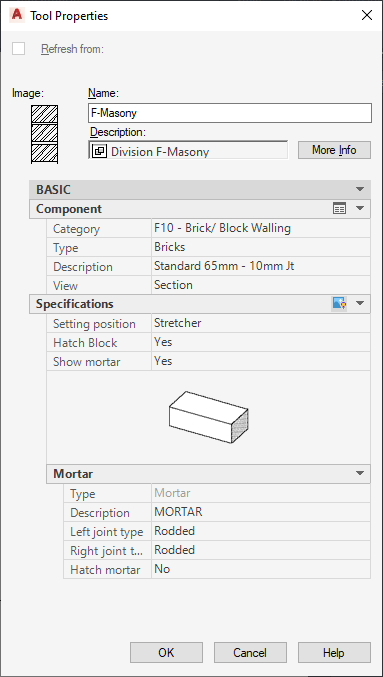
Detail component Tool Properties worksheet configurations
The following table describes the Tool Properties worksheet categories and settings that are common to most detail component insertion tools.
| Property/Category Name | Description |
|---|---|
| Image | Displays the image specified for the component in its table in the database. If no image is specified, then the image for the table is displayed. You can right-click the image and click Refresh Image to recall the stock image for the tool from the database, or you can right-click and click Specify Image to browse for a different image. |
| Name | The name of the tool. This may be the name originally assigned to one of the tools on the sample palettes, or, if you have copied the tool from the Detail Component Manager, it is the name specified in the Description column of its parent size table. Note that the name is not updated if you change the Category, Type, or Size properties under Component. However, you can edit the name. |
| Description | This is the tool description used if the tool is published to a catalog. You can change this description by clicking the worksheet icon to open a Description editing box. |
| Component | Clicking the worksheet icon on this line accesses the Detail Component Manager through the Select Component dialog box and allows you to change the settings for the Description, Description and Type, or Description, Type, and Category. Note that if you change the Category setting, the Name, Description, and Image properties are not updated automatically. |
| Category | Specifies the group or subgroup that is the parent of the table containing the component specified by the Description property. If other groups or subgroups exist at the same hierarchical level within the same parent group, they are selectable from a drop-down list. |
| Type | Specifies the table containing the particular component specified by the Description property. A drop-down list lets you select other tables within the same parent group or subgroup. |
| Description | Specifies a particular component of the specified Type and Category. Other components within the same table can be selected from the drop-down list. |
| View | Specifies the type of view for which the component is oriented. Possible values are Section, Plan, Elevation, and Elevation (Pattern). For components such as bolts, component-specific terminology is used, such as Head, Side, Bolt, or Nut. A drop-down list is present if more than one view is applicable for the specified component. This setting determines the drawing routine and the command line prompts for the insertion process. |
| Specifications | Clicking the icon on this line displays of an image depicting the orientation at which the detail component will be inserted (determined by the View property). Other properties displayed here provide the top-level parameters required to insert the component with the specified View setting. For components with only one possible View setting, no Specification properties are displayed. |