AutoCAD Architecture 2022 toolset uses the same basic customizable tool for adding the following types of annotations to drawings:
- Multiline text notes with single or multiline leaders
- Symbol-based notes with attributes
- Reference keynotes
- Sheet keynotes
- Break marks
The specific type of annotation, its appearance, and other characteristics are determined by editable values on the Tool Properties worksheet, which is accessed from the context menu of the tool. Annotation objects are created at a scale based on the specified annotation scale.
Several default versions of this annotation tool are provided with the software, each representing a different configuration of the Tool Properties worksheet. Depending on how your system is set up, you may find one or more of these tools (or locally customized versions of them) on the sample Annotation tool palette in the workspace. These tools are also available from the Stock Tools Catalog and the Documentation Tool Catalog in the Content Browser. Using the i-drop feature, you can copy any of these tools to a tool palette in the workspace and customize it to meet your needs.
The basic annotation tool lets you insert either text-based or block-based annotations. In both cases, the annotation can be created with or without a leader that connects it visually to a particular object or point in the drawing. The annotation tool also supports keynoting, where a predefined keynote is retrieved from a database, either through direct selection or automatically, based on a selected object within the drawing. Generally, text-based annotations are used for reference keynoting, and block-based annotations are used for sheet keynoting. However, the annotation tool accommodates many different styles of drawing annotation, such as break marks.
Annotation Tool Properties
The following illustrations show the Tool Properties worksheet settings for two of the default versions of the annotation tool: the text-based Text (Straight Leader) tool and the block-based Square (Straight Leader) tool. Note the different values for Content type under the General category. When the content type is multiline text (Mtext), additional settings are displayed under the Text category. Likewise, when the content type is Block, settings are displayed for Symbol and Symbol location. The settings available under the Leader category also vary based on the current value for Leader type.
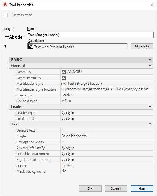
MText annotation tool properties
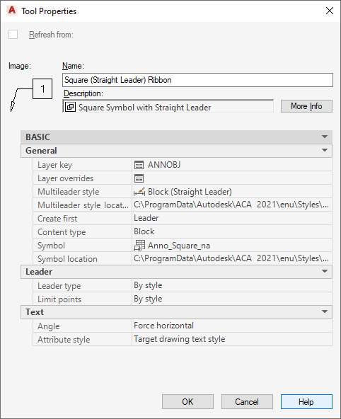
Block annotation tool properties
The following table lists and describes the annotation tool properties that can be configured through the Tool Properties worksheet. Once an annotation is inserted into a drawing, properties of the annotation or its leader can be modified using the associated Properties palette.
| Property Category/Name | Description |
|---|---|
| General/Layer key | Specifies the layer key for the layer to which annotation is assigned. To change, click the current value (default is ANNOBJ) to access the Select Layer Key dialog box. |
| General/Layer override | Specifies one or more layer key overrides. Click the worksheet icon to access the Select Layer Overrides dialog box. |
| Multileader style | Specifies the multileader style for the annotation. Possible styles include Text, Block, and Standard. |
| General/Content type | Possible values are Mtext (for basic multiline text notes and reference keynotes) or Block (for symbols with attributes and sheet keynotes). When inserting an Mtext object using default settings, you are prompted to specify text width. |
| General/Symbol | Displayed only if Content type is Block, this property specifies the block-based symbol to be used for the annotation. For sheet keynotes, the block contains an automatically updatable field value that determines keynote format and either specifies a particular keynote or serves as a placeholder. The placeholder value is then replaced by whatever keynote is associated with the selected object or component or by a keynote selected manually during the insertion process. |
| General/Symbol location | The location of the drawing file containing the specified symbol. Click the property and use the Browse option from the drop-down list to locate and enter the path to the file. If this property is unspecified (--), then only those blocks in the current drawing file are listed. |
| Leaders/Leader type | Possible values are None, Straight, or Spline. |
| Leaders/Leader dimension style | By default, this property is unspecified (--), and the dimension style for the current drawing is used. Or you can click the property and select a style from the drop-down list. The style controls the leader arrow head as well as the text options as set on the Text tab of the style. |
| Leaders/Leader dimension style location | Specifies the location of the dimension style if different from the current drawing dimension style. Click the property and use the Browse option from the drop-down list to locate and enter the path to the selected style. If this property is unspecified (--), then only those styles in the current drawing are used. |
| Leaders/Limit points | Displayed only if a leader type is specified, this property indicates whether there is a limit to the number of points in the leader. If unspecified (--), the corresponding leader setting for the current drawing is used. |
| Leaders/Maximum points | Displayed only if the Limit points setting is yes, this property specifies the maximum number of points allowed in the leader before the text or symbol is inserted. If unspecified, the corresponding leader setting for the current drawing is used, if applicable. |
| Text/Default text | Displayed only if Content type is Mtext. For basic text notes, this value is unspecified (--), and you enter the text upon insertion. For reference keynotes, the value should be a placeholder keynote field. The placeholder value is then replaced by whatever keynote is associated with the selected object or component, or by a keynote selected manually during the insertion process. |
| Text/Angle | Specifies the angle for multiline text or attribute text. The default is Force horizontal. Other drop-down list options are As inserted (which sets text rotation at the angle of the last leader segment) and Right reading (which keeps the text right-side up regardless of rotation angle). |
| Text/Attribute style | Displayed only if Content type is Block, this property specifies whether attribute text within the symbol uses the target drawing text style or the style defined by the attribute tag. |
| Text/Prompt for width | Indicates whether you are prompted to specify a width for the annotation. If unspecified (--), the corresponding leader setting for the current drawing is used. |
| Text/Always left justify | Displayed only if Content type is Mtext and Leader type is other than None, this property specifies whether each word in the annotation text is always left-justified. If unspecified (--), the corresponding leader setting for the current drawing is used. |
| Text/Left side attachment | Displayed only if Content type is Mtext and Leader type is other than None, this property specifies where text attaches to a leader positioned to its left. This setting can be selected from a drop-down list. If unspecified (--), the corresponding leader setting for the current drawing is used. |
| Text/Right side attachment | Displayed only if Content type is Mtext and Leader type is other than None, this property specifies where text attaches to a leader positioned to its right. Setting can be selected from drop-down list. If unspecified (--), the corresponding setting for the current drawing is used. |
| Text/Underline bottom line | Displayed only if Content type is Mtext and Leader type is other than None, this property specifies whether a leader attaches to text as an underline below the bottom line of text. If unspecified (--), the corresponding leader setting for the current drawing is used. |
| Text/Frame | Displayed only if Content type is Mtext and Leader type is other than None, this property specifies whether text is enclosed in a frame. If unspecified (--), the corresponding leader setting for the current drawing is used. |
| Text/Mask background | Displayed only if Content type is Mtext, this property specifies whether text has an opaque background to mask out objects below it. The default setting is No. |
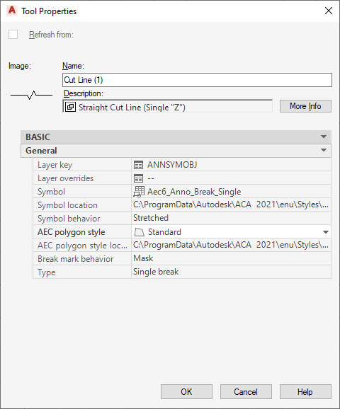
Break Mark Tool Properties
Block-based break mark tools are used to mask or trim underlying objects with a polyline and an AEC polygon. The default break mark tool is the Cut Line tool provided on the Annotation tool palette. Additional types of break marks are available from the Stock Tool and Documentation Catalogs of the Content Browser.
The following table lists and describes tool properties for break marks that can be configured through the Tool Properties worksheet. Once a break mark is inserted into a drawing, its properties can be modified using the associated Properties palette.
| Property Category/Name | Description |
|---|---|
| Layer key | Specifies the layer key for the layer to which the break mark is assigned. To change, click the current value (default is ANNSYMOBJ) to access the Select Layer Key dialog box. |
| Layer override | Specifies one or more layer key overrides. Click the worksheet icon to access the Select Layer Overrides dialog box. |
| Symbol | Specifies the block-based symbol to be used for the break mark. For sheet keynotes, the block contains an automatically updatable field value that determines keynote format and either specifies a particular keynote or serves as a placeholder. The placeholder value is then replaced by whatever keynote is associated with the selected object or component or by a keynote selected manually during the insertion process. |
| Symbol location | The location of the drawing file containing the specified break mark symbol. Click the property and use the Browse option from the drop-down list to locate and enter the path to the file. If this property is unspecified (--), then only those blocks in the current drawing file are listed. |
| Symbol behavior | Specifies whether the break mark inserts as Scaled or Stretched. If Stretched is selected, the cut line is stretched to correspond with the start point and endpoint, but the graphic of the cut remains the same. If Scaled is selected, the graphic in the cut line is scaled to correspond with the start point and endpoint of the cut line. |
| AEC polygon style | Specifies whether the break mark has masking properties. If this property is unspecified (--), the style defaults to the standard style. |
| AEC polygon style location | Specifies the location of the drawing file containing the AEC polygon. Click the property and use the Browse option from the drop-down list to locate and enter the path to the file. If this property is unspecified (--), then only those AEC polygons in the current drawing file are listed. |
| Break mark behavior | Specifies whether the break mark masks or trims the underlying object. An AEC polygon and a polyline together represent the mask behavior of a break mark and do not modify the underlying object. A polyline represents the trim behavior of a break mark and clips the underlying object. |
| Type | This property specifies whether the cut line is represented by a single edge of an AEC polygon (single break) or two parallel edges of an AEC polygon (dual break). |