Database links require a link template that identifies which table fields are associated with which link using that template.
Connectivity
Database connectivity associates objects in a drawing with external data store in database programs such as dBASE, Oracle, or Microsoft Access. For example, you can associate information contained in a room database with a polyline object representing a room boundary in a drawing. The association between the graphical object and the database table is established by creating a link, which references one or more records in the database table.
Links and Link Templates
You cannot create links to nongraphical objects such as layers and linetypes.
Links are tightly connected with the graphical objects they are associated with. If you move or copy a linked object, the link is moved or copied with it. If you delete a linked object, the link is also deleted.
When you create a link, a dynamic relationship is established between the database record and the object. If, for example, you change a room type in the database table from a storage area to an office, the program updates the information stored in the drawing.
Links are based on link templates, which define what information is to be retrieved from the database table when the links are created.
Link templates also function as shortcuts to the database tables that they're based on. Using the shortcuts you can open the database tables that they reference for viewing or editing. This is particularly useful if you have a large number of data sources configured on your system. Rather than scrolling through a list of data sources each time you want to locate an individual database table, you can open it directly from the drawing node of the drawing that it is associated with.
Automatic Selection of Linked Objects
You can set up the program to automatically select linked graphical objects in your drawing as additional records are selected in the Data View window. Conversely, you can set up the program to select linked database records as additional graphical objects are selected in your drawing. Only one of these automatic viewing modes can be active at a time.
Other Display Options
You can use the Data View and Query Options dialog box to set a number of viewing options that affect how linked records and linked graphical objects are displayed whenever a corresponding linked item is selected.
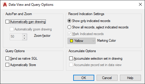
The Automatically Pan Drawing option automatically pans the drawing to display objects that are associated with the current selection set of records in the Data View window. If you have multiple records selected in the Data View window, AutoPan may not be able to fit all of them in the drawing window with your drawing's current zoom factor. To control for this, you can set a zoom factor for the AutoPan mode that ensures that all linked objects associated with the current record set are displayed.
The Automatically Zoom Drawing option automatically zooms the drawing so that all objects associated with the current record set are displayed. You must specify a zoom factor that sets the size of the extents of the indicated object set to a defined percentage of the drawing area. The available range is 20 percent to 90 percent, and the default value is 50 percent. A value of 50 percent means that either the height of the extents is 50 percent of the height of the drawing area, or the width of the extents is 50 percent of the drawing area, whichever is less.
- Record Indication Settings. Specify whether all records or only the subset associated with the current selection set of graphical objects are displayed in the Data View window. If the Show All Records, Select Indicated Records option is selected, you can specify a marking color to apply to the linked records.
- Accumulate Options. Specify whether the program accumulates selection sets of linked graphical objects or Data View records, or creates new selection sets as additional objects or records are selected.
For a description of all the options available, see Data View and Query Options Dialog Box under DBCONNECT in the Command Reference.
Find and Correct Link Errors
It is recommended that you periodically check the links in your drawings to update or delete broken links. The program provides a Synchronize option to analyze the links in a drawing that are based on a particular link template. After you run the Synchronize option, a list of detected errors is provided in the Synchronize dialog box. Certain errors (such as a resized column in the source database table) can be fixed directly from the Synchronize dialog box. Other errors (such as links that point to non-existent records) must be fixed in the source database table.