Creates a smooth curve that passes through or near a set of fit points, or that is defined by the vertices in a control frame.
SPLINE creates curves called nonuniform rational B-splines (NURBS), referred to as splines for simplicity.
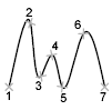
Splines are defined either with fit points, or with control vertices. By default, fit points coincide with the spline, while control vertices define a control frame. Control frames provide a convenient method to shape the spline. Each method has its advantages.

To display or hide the control vertices and control frame, select or deselect the spline, or use CVSHOW and CVHIDE. However, for splines created with control vertices in AutoCAD LT, you can display the control frame only by selecting the spline.
The prompts differ, depending on whether you choose Fit or CV (control vertices) as the creation method (Method option).
First Point
Specifies the first point of the spline, either the first fit point or the first control vertex, depending on the current method.
- Next Point
-
Creates additional spline segments until you press Enter.
- Undo
- Removes the last specified point.
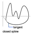
- Close
-
Closes the spline by defining the last point to be coincident with the first. By default, closed splines are periodic, maintaining curvature continuity (C2) along the entire loop.
Method
Controls whether the spline is created with fit points or with control vertices. (SPLMETHOD system variable)
- Fit
-
Creates a degree 3 (cubic) B-spline by specifying fit points that the spline must pass through. When the tolerance value is greater than 0, the spline must be within the specified tolerance distance from each point.
- Control Vertices (CV)
-
Creates a spline by specifying control vertices. Use this method to create splines of degree 1 (linear), degree 2 (quadratic), degree 3 (cubic), and so on up to degree 10. Adjusting the shape of a spline by moving control vertices often provides better results than moving fit points.
Object
Converts 2D or 3D quadratic or cubic spline-fit polylines to equivalent splines. The original polyline is retained or discarded depending on the setting of the DELOBJ system variable.
Prompts for Splines with Fit Points
The following prompts are specific to the fit point method.
- Knots
-
Specifies the knot parameterization, one of several computational methods that determines how the component curves between successive fit points within a spline are blended. (SPLKNOTS system variable)
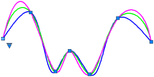
- Chord. ( Chord-Length method) Spaces the knots connecting each component curve to be proportional to the distances between each associated pair of fit points. An example is the green curve in the illustration.
- Square root. (Centripetal method) Spaces the knots connecting each component curve to be proportional to the square root of the distance between each associated pair of fit points. This method usually produces “gentler” curves.
- Uniform. (Equidistant method). Spaces the knots of each component curve to be equal, regardless of the spacing of the fit points. This method often produces curves that overshoot the fit points.
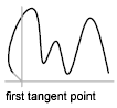
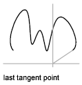
- Start Tangency
-
Specifies a tangent condition on the starting point of the spline.
- End Tangency
-
Specifies a tangent condition on the ending point of the spline.
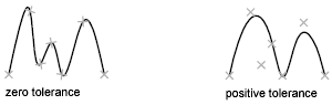
- Tolerance
-
Specifies the distance by which the spline is allowed to deviate from the specified fit points. A tolerance value of 0 requires the resulting spline to pass directly through the fit points. The tolerance value applies to all fit points except the starting and ending fit points, which always have a tolerance of 0.
Prompts for Splines with Control Vertices
The following prompt is specific to the control vertices (CV) method. (SPLMETHOD system variable)
- Degree
-
Sets the polynomial degree of the resulting spline. Use this option to create splines of degree 1 (linear), degree 2 (quadratic), degree 3 (cubic), and so on up to degree 10.