A spline is a smooth curve that passes through or near a set of points that influence the shape of the curve.
By default, a spline is a series of blended curve segments of degree 3 (also called cubic) polynomials. These curves are technically called nonuniform rational B-splines (NURBS), but are referred to as splines for simplicity. Cubic splines are the most common, and mimic the splines that are created manually using flexible strips that are shaped by weights at data points.
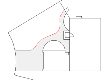
In the following example, a spline was used to create the highlighted boundary of the concrete walkway.
Understand Control Vertices and Fit Points
You can create or edit splines using either control vertices, or fit points. The spline on the left displays control vertices along a control polygon, and the spline on the right displays fit points.
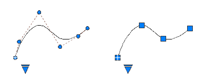
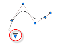
Use the triangular grip on a selected spline to switch between displaying control vertices and displaying fit points. You can use the round and square grips to modify a selected spline.
Create Splines Using Fit Points
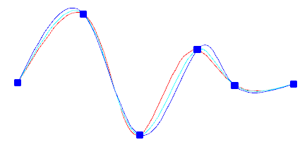
When you create splines using fit points, the resulting curve passes through the specified points, and is influenced by the spacing of mathematical knots in the curve.
You can choose the spacing of these knots with the knot parameterization option, which will result in different curves as shown in the example.
When the Tolerance value is set to 0, the spline passes directly through the fit points. With larger tolerance values, the spline passes near the fit points. Optionally, you can specify the tangent direction for the spline at each end.
Special Cases
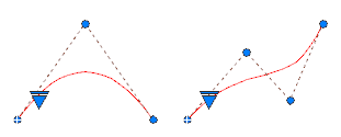
You can create a spline with a parabolic shape by specifying a degree 2 spline created with exactly 3 control vertices as shown on the left. Degree 3 splines created with 4 control vertices have the same shape as Bezier curves of degree 3 as shown on the right.
