Several methods are available for editing splines and changing their underlying mathematical parameters.
You can edit splines using multifunctional grips, SPLINEDIT, and the Properties palette. In addition to these operations, splines can be trimmed, extended, and filleted.
Edit Splines with Multifunctional Grips
Multifunctional grips provide options that include adding control vertices and changing the tangent direction of the spline at its endpoints. Display a menu of options by hovering over a grip.
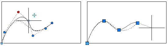
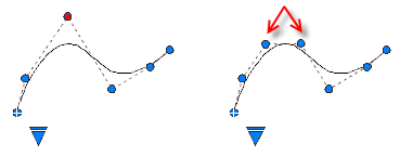
The editing options available with multifunctional grips differ depending on whether the spline is set to display control vertices or fit points. The spline on the left displays control vertices, and the one on the right displays fit points.
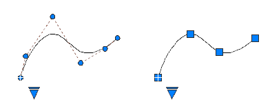
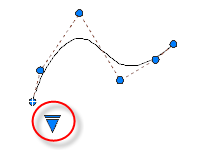
To switch between displaying control vertices and displaying fit points, click the triangular grip.
In general, editing a spline with control vertices provides finer control over reshaping a small section of the curve than editing a spline with fit points.
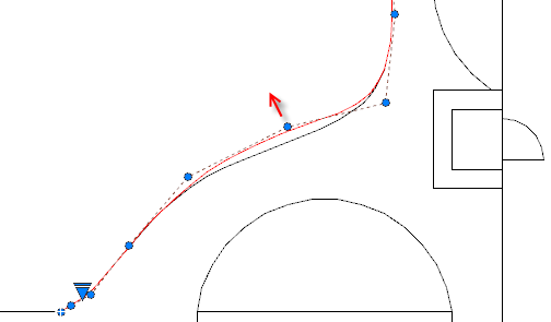
You can insert additional control vertices to a section of a spline to obtain greater control in that section at the expense of making the shape of the spline more complicated. The Refine option adds a knot to the spline resulting in replacing the selected control vertex with two control vertices.
Edit Splines with SPLINEDIT
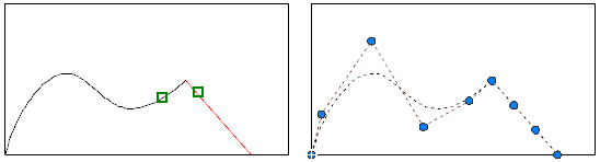
SPLINEDIT provides additional editing options, such as adding a kink to the spline, and joining a spline to another contiguous object, such as a line, arc, or other spline. As shown, objects are joined to splines with C0 continuity.
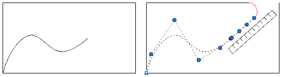
Edit Splines with 3DEDITBAR
(Not available in AutoCAD LT)
3DEDITBAR displays a gizmo that can move a portion of a spline proportionately, or change the direction and magnitude of the tangent at a specified base point on the spline. To display a menu of control options, right-click the gizmo.
The gizmo in the illustration is the default setting, which is the Move Point Location option. The square grip is located at a specified base point on the spline, and is used to stretch a portion of the spline.
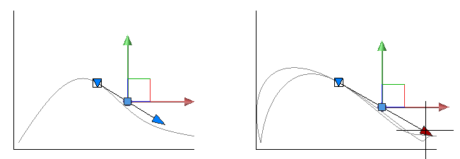
The red and green axis arrow grips constrain the movement of the square grip in their respective directions.
Click the downward-pointing triangular grip to switch to the Move Tangent Direction option as illustrated below. Even though the axes of the gizmo change their location, the base point remains the same. With this option, moving the square grip changes the slope of the tangent at the base point.
The tangent arrow grip changes the magnitude of the tangent at the base point, creating either a sharper or a flatter curvature at the base point. In the illustration, the magnitude of the tangent is being increased.
Edit Splines with a Palette
The Properties palette provides access to several spline parameters and options, including the degree of the spline, the weight for each control point, the knot parameterization method used in conjunction with fit points, and whether the spline is closed.
Trim, Extend, and Fillet Splines
Trimming a spline shortens it without changing the shape of the portion that remains. Extending a spline lengthens it by adding a linear portion that is tangent to the end of the spline (C1 continuity). If the shape of the spline is later changed, the tangency of the linear portion is not maintained.
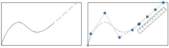
Trimming a spline shortens it without changing the shape of the portion that remains.
Filleting a spline creates an arc that is tangent to the spline and the other selected object. The spline might be extended with a linear portion to complete the fillet operation.