You can generate detail views with rectangular or circular borders from any model documentation drawing view.
Note: Model documentation is available only on 64-bit systems.
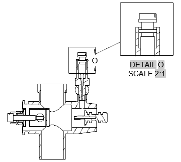
Create a Detail View with a Rectangular Boundary
- Click . Find
- Click the view to use as the parent view.
Tip: The format of the detail view is controlled by the current detail view style. You can override these settings using the Detail View Creation Ribbon Contextual Tab. For example, you can specify the detail view identifier, scale and visibility of the detail view label.
- Click the center of the area to magnify.
- Click a corner to define the area to magnify. The detail view identifier is placed at the place you clicked and a preview of the detail view appears at the cursor.
Note: If required, you can reposition the identifier after you create the detail view.
- Move the preview to the appropriate location and click to place the view.
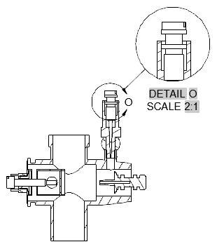
Create a Detail View with a Circular Boundary
- Click . Find
- Click the view to use as the parent view.
Tip: The format of the detail view is controlled by the current detail view style. You can override these settings using the Detail View Creation Ribbon Contextual Tab. For example, you can specify the detail view identifier, scale and visibility of the detail view label.
- Click in the drawing area to define the center of the area to magnify.
Note: If infer constraints is on, (CONSTRAINTINFER=1), a coincident constraint is applied to this point.
- Click to specify the diameter of the area to magnify. The detail view identifier is placed at the place you clicked and a preview of the detail view appears at the cursor.
Note: If required, you can reposition the identifier after you create the detail view.
- Move the preview to the appropriate location and click to place the view.