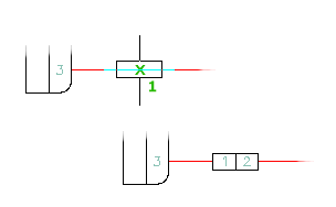
The splice symbol is an in-line connection symbol allowing one or more wires to connect at each end. The default splice symbol triggers a wire number change through the symbol.

- Click


 . Find
The Splice Symbols dialog box displays.
- Select the splice to insert from the icon menu, enter the splice name in the Type it box, or click Browse to browse to and select the symbol from another location.
- Click OK.
- Pick the insertion point on the drawing. Place the symbol on an existing wire, causing the symbol to break the wire or place it in empty space (where you can later draw a wire through the symbol or connect one or more wires to each end of it).
The Insert/Edit Component dialog box displays.
- Assign the catalog information, description, and other information as required.
- Click OK.