In this exercise, you create a power supply using the Symbol Builder tool.
- In an AutoCAD drawing, draw a rectangle on the drawing.
 Note: You can also create and modify the graphics for the symbol in the Block Editor environment.
 - Click
 . Find
- In the Select Symbol/Objects dialog box, Attribute template section, browse to the Library path C:\Users\Public\Documents\Autodesk\Acade {version}\Libs\jic125.
- In the Attribute template section, choose Symbol: Horizontal Parent.
- In the Attribute template section, choose Type: Generic.
- In the Select from drawing section, click Select objects and select the rectangle.
- Select OK.
Add attributes
In this part of the exercise, you insert some AutoCAD Electrical toolset attributes from the Symbol Builder Attribute Editor. You are not limited to these attributes, and you can include your own user-defined attributes on the AutoCAD Electrical toolset block files.
- If the Symbol Builder Attribute Editor is not visible,
Click
. Find
- Select the TAG1 attribute.
-
 Select the Properties tool to launch the Insert/Edit Attributes dialog box.
- Change the height to 0.125 and Justify to Center.
- Enter “PS” as the Value. It is the default code used as the %F value of the tag format (such as “CR” , “PB”, “LT”)
- Select OK.
-
 Click the Insert Attribute tool.
- Select an insertion point for the attribute.
Note: You can also right-click and select Insert Attribute or drag the attribute to insert it.
-
Select DESC1, click the Insert Attribute tool, and insert it below TAG1.

- Repeat to insert the INST and LOC attributes above TAG1.
- Select MFG, CAT, and ASSYCODE. Click the Insert Attribute tool, and insert them near the center of the rectangle.
Note: If the CAT and ASSYCODE attributes are not listed they are inserted with MFG as a group.
- Repeat to insert the FAMILY attribute near the center of the rectangle.
-
With FAMILY still highlighted in the Symbol Builder Attribute Editor, select the Properties tool. Enter “PS” as the Value and OK. This assigns the %F value to the FAMILY attribute inserted.

Add wire connection attributes
You can define wire connection points and terminal text for the library symbol. When you add a wire connection, you select the style, the direction the wire connects from, and whether to include the optional TERMxx and TERMDESCxx attributes. In this exercise, wire connection attributes are inserted at the left, bottom, and right side of the symbol.
- If the Symbol Builder Attribute Editor is not visible,
Click
. Find
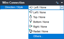
- Expand the Wire Connection section of the Symbol Builder Attribute Editor.
- Expand the Direction/Style list and select Others to launch the Insert Wire Connections dialog box.
- On the Insert Wire Connections dialog box, select Terminal Style: Screw.
- Select Connection Direction: Left.
- Check Use this configuration as default. This directs Symbol Builder to use the current Terminal Style and Scale as the default in the drop-down list.
- (Optional) Enter “L1” as the TERM01 value. This sets “L1” as the default terminal pin number when the symbol is used.
- (Optional) Select X4TERMDESC01 in the Pin Information section and click Delete. This directs Symbol Builder not to insert the optional attribute with the wire connection attribute.
- Click Insert and select in the center of the left-hand side of the rectangle as shown. The wire connection attribute, X4TERM01, and the terminal pin attribute, TERM01, are inserted.

- Back on the Symbol Builder Attribute Editor, expand the Wire Connection list and select Bottom/Screw.

-
 Select the Insert Wire Connection tool and insert the terminal in the bottom center of the rectangle.
- Select Right/Screw from the Wire Connection Direction/Style list.
- Select the Insert Wire Connection tool and insert the terminal in the center of the right-hand side of the rectangle.

- In the Pins section, enter “GND” in the TERM02 value, and “L2” in the TERM03 value.

Finishing the parent symbol
-
Click
. Find
- Click Base Point: Pick point and select the center of the rectangle.
- Select Wblock. Wblock creates the symbol .dwg file, while Block creates the symbol for this drawing file only.
- Enter the Name and file path or keep the default. AutoCAD Electrical toolset provides a default name for the new symbol based on the attribute template selected. Avoid changing the first four letters of the file name and limit the total length to 32 characters.
- (Optional) If you are going to add the symbol to the icon menu at a later time using the Icon Menu Wizard, check Icon image. Enter the image name and folder.
- (Optional) Click Details to see the Symbol Audit dialog box listing potential issues with your symbol.
- Select OK.
- Select Close Block Editor from the block editor toolbar.
- (Optional) Select Yes to insert the symbol on the drawing and select a location. If you place the component on an existing wire, the wire breaks. The component tag is assigned.
Additional options
The additional options for creating a symbol listed are not used for this example, but you can use them when creating your own symbol.
-
Optional Attributes: The attributes listed in this section are allowed on a parent symbol. You can also add attributes to the Required or Optional list using the following steps.
-
 Select the Add Attribute tool to launch the Insert/Edit Attributes dialog box.
- Enter the attribute name as the Tag value.
- Enter all property values.
- Click Insert to insert the attribute or OK to add it to the list without inserting it.
-
-
Link Lines:
Inserts Link Line attributes so the program can draw dashed link lines between a parent symbol and its related child contact. It requires special attributes at the point where the dashed line connects to the symbol.
- Expand the Link Lines section.
- Select a direction from the Direction list.
-
 Select the Insert Link Lines tool.
- Select a location for the Link Line attribute.
-
RATING or POS sections: You can add up to 12 Rating and Position attributes. If the attribute template contains a RATING1 or POS1 attribute, or you add one, these sections are available on the Symbol Builder Attribute Editor.
- Expand the RATING or POS section.
-
 Select the Add Next tool.
- Pick an insertion point.
-
Convert Text to Attribute dialog box: If you selected existing text entities from the Select Symbol/Objects dialog box, or added text while in the Block Editor environment, this option converts existing text entities to AutoCAD Electrical toolset attributes in the same location as the original text.
-
 Select the Convert Text to Attribute tool from the Symbol Builder toolbar to launch the dialog box.
- Select a text entry in the list and click the arrow pointing at the attribute name.
- Repeat for all text entities.
- Click Done. The text entity is converted to the attribute. The text value becomes the default value for the attribute.
-
-
Convert text: If you selected existing text entities from the Select Symbol/Objects dialog box, or added text while in the Block Editor environment, this option converts a single text entity to an AutoCAD Electrical toolset attribute in the same location as the original text.
- Select an attribute on the Symbol Builder Attribute Editor.
-
 Select the Convert Text tool.
- Select the text entity. The text entity is converted to the attribute. The text value becomes the default value for the attribute.
- Audit Symbol: At any time you can audit the symbol to find any potential issues with your symbol and symbol name.