Cross-referencing is based on collecting and annotating groups of components that carry the same TAG text string value (for example, 101CR). Components do not have to be of the same family to be cross-referenced, but they must have the same TAG1/TAG2/TAG_*/TAG attribute values.
Three cross-reference format are supported:
- Text
- Graphical
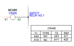
- Table
Text cross-reference is annotated on to attributes XREFNO and XREFNC for N.O and N.C. references respectively. Alternately, if attribute XREF is present, both N.O. and N.C. references are combined into a single cross-reference text string. Graphical and table cross-reference use these attributes for placement location.
The AutoCAD Electrical toolset Component Cross-reference tool creates two text reports in the process of annotating components with cross-reference information. The Cross-reference report gives a listing of each component and quantity and locations of child contacts. The Exception/Error report lists the exceptions AutoCAD Electrical toolset found as it processed the drawing or drawing set. Exceptions include child contact with no parent and parent relay coil with no child contacts found.
Cross-reference settings are supported at the project, drawing, and component level.
|
Project Cross-Reference Settings |
Settings are maintained inside of the project definition file (.wdp). Once settings are created for the project, AutoCAD Electrical toolset applies those settings to new, existing, and copied drawings inside of the project. Ultimately, cross-reference settings are written to the WD_M block of the drawing file to use during normal operations. |
|
Drawing Cross-Reference Settings |
Settings are maintained on the WD_M block of the drawing. When the cross-reference command is run, AutoCAD Electrical toolset uses the drawing settings to determine the cross-reference types. During program runtime, the cross-reference command looks at the WD_M block as the definition for all referencing on the drawing. |
|
Component Cross-Reference Settings |
Settings are maintained at the component to override the drawing's WD_M block settings of the drawing. During program runtime, the cross-reference command first looks to the component definition before the WD_M block as the definition for referencing the component on the drawing. |
During normal operation of cross-referencing commands, AutoCAD Electrical toolset looks to the component for its settings information before using the drawing settings. If the component has settings defined, they are used. If there are both component and drawing cross-reference settings on the same drawing, the component settings are used where applied and the drawing settings are used for the rest of the components.