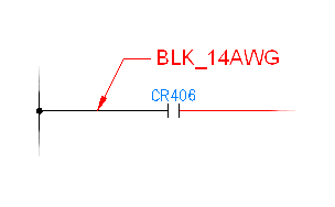
When you select a wire to label, AutoCAD Electrical toolset reads the layer name of the wire, retrieves the matching text label, and inserts it as a label/leader on the drawing. The resulting wire color/gauge label is automatically revised if you change the wire layer of a labeled wire.
In Setup, set the default color/gauge text string, text size, arrow size, gap size, and arrow type for the wire label/leaders. In the Create/Edit Wire Type dialog box, add new wire layer names.
The mapping file is an ASCII text file with a ".wdw" extension. The default mapping file, default.wdw, is referenced if a project-specific .wdw file is not found. The mapping file lists each wire layer name followed by the wire color/gauge label text to assign to that wire layer.
You can easily set up or edit these labels. Select the wire color/gauge tool and select Setup to display the setup dialog. All the valid layer names of the current drawing are listed in the upper dialog box list along with any matching labels found in the ".wdw" file (if it exists). Highlight any layer name and type in the label you want to associate with it. Use the "|" character to trigger a line break within your label text. For example, "RED_14_THHN:RED|AWG#14" causes wire labels for layer "RED_14_THHN" to display as two-line "RED" and "AWG#14" labels. Your entries are saved to the ".wdw" file for instant reference as you insert wire color/gauge labels.
About Automatic Wire Leaders
AutoCAD Electrical toolset places wire numbers on leaders when it determines that the wire number text bumps into something (it does not check if the leader itself collides with something). AutoCAD Electrical toolset first makes 15 tiny step checks in the "up" direction. If it fails it checks 15 steps in the down direction. If it fails, it tries at approximately 60-degree angles. If all checks fail, it leaves the wire number where it originally was going to put it. This entire process takes just a split second.
Leader checks are triggered when wire numbers are inserted or they re-center due to an adjacent SCOOT operation. If a component is scooted and the result is enough room for a wire number on a leader to do without the leader, AutoCAD Electrical toolset automatically removes the leader and positions the wire number just above the wire.