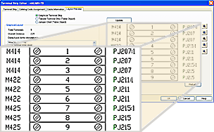
Use terminal blocks to connect devices that require quick disconnect or disassembly during product shipment, while at other times they can be used to distribute power to other devices. The Terminal Strip Editor defines the locations for these connected devices during the system design process. Terminal strip editing is primarily used towards the end of the control system design cycle to expedite the labeling, numbering, and rearranging of terminals on a terminal strip.
A document that is created to facilitate the construction of a terminal strip and all of its wiring is a terminal strip layout drawing. These drawings display the general arrangement of all the terminal blocks that belong to a specific terminal strip. You can also display the wiring and device connection information next to the terminal block symbol using the Terminal Strip Editor. You can rely on the terminal strip layout drawing for all information regarding the terminal strip without having to reference the schematic drawings.
Modifies an entire terminal strip or individual terminals. Assigns catalog values, resequences terminal numbers, adds jumpers and jumper charts, adds spares and accessories. Inserts or updates graphical or tabular terminal strip layouts.

The Installation (INST), Location (LOC) and Tag Strip (TAG_STRIP) values are used to determine the uniqueness of a terminal strip no matter which standard is used in the active project (such as Combined Installation/Location tag mode).
After changes are made with the Terminal Strip Editor, the changes are written back to the schematic drawing for future updates, and a graphical or tabular drawing of a terminal strip layout is created. Your drawing must be part of the active project to perform updates.
If the Terminal Strip Editor encounters an error and is unable to start, a log file (named TSE_Error_<date and time>.log) is created in the same location as the project file. The log information includes details about the user name, project name, date, time, terminal strip tag, installation, and location. It also includes details about the specific terminal such as the drawing it is on, the handle of the terminal, and the issue with the terminal.
Wiring Constraints
The Terminal Strip Editor can add or remove extra terminals based on the assigned wiring constraints. Wiring constraints is the limitation of the number of wires that can be connected to a particular device (for example, terminal). When modifying terminals, you can assign the number of wires allowed for each side of the terminal in the Wires Per Connection section of the Terminal Block Properties dialog box.
Extra terminals get placed only when editing a terminal using the Terminal Strip Editor. Once you define the Wires Per Connection value, the Terminal Strip Editor checks to see if there are more wires/devices connected to a side of the terminal than what is allowed. If it finds the defined constraint to exceed, the Terminal Strip Editor adds an additional terminal and moves the destination that is exceeding the constraint to the new terminal. The new terminal has the same destination, property, and catalog assignment as the original terminal. The moved destination is placed in the same level of the new terminal as it was in the original terminal. The extra terminals are reflected in the Bill of Materials.
When a terminal strip is edited with the Terminal Strip Editor, the need for extra terminals is re-evaluated and they are removed if the constraints are no longer exceeded. If the main footprint terminal is removed from the association, the extras are removed.
Terminal Strip Table Generator
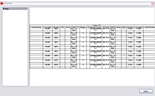
Terminal Strip Table Generator inserts one terminal strip or multiple terminal strips as table objects. It places all table sections on new drawings, and adds new drawings to the active project.

There are options to insert a terminal strip as a single table object or to split the terminal strip into multiple table objects. This tool can also be used to rebuild or refresh existing terminal strip tables within the active project.
Each terminal strip selected begins on a separate drawing. The installation code, location code, and tag values of the terminal strip are written to the Drawing Description Field inside of the project file (*.wdp).