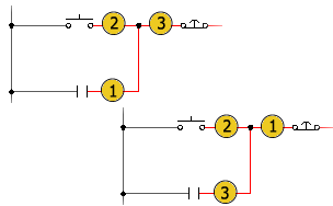
Defines a wire connection sequence to control wire from/to reporting.
Find Command entry:
AEEDITWIRESEQUENCE
Predefine the connection sequence of a wire network. The network can be fully contained on the active drawing, or can pass across multiple drawings using signal source/destination symbols.

Defining the sequence gives you control over how AutoCAD Electrical toolset analyzes the circuits including:
- The order of the contents in the WFRM2ALL table in the project database file
- How from/to connection information is output to various reports
- Annotation on physical footprint representations (using the Wire Annotation of Panel Footprint tool).
 Edit Wire Sequence.
 Provides these features to define the sequence order:
- Sort the components by physical location.
- Move the components up or down in the listing.
- Pick mode, in the active drawing only, where you pick the wire connection points to define the connection sequence.
Once you specify the sequencing, you can use the Show Wire Sequences tool to view the sequence or use the Wire From/To reporting tool to see how the sequencing is reported.
|
Wire Connection Sequence |
Lists the wires and terminals found in the circuit. "*" - indicates that the wire is on another drawing. “t” - indicates that the entry is a terminal and a candidate for a direct-to-terminal secondary sequence definition.
Note: Components connected on the far side of a terminal (on a side opposite of the picked wire network) are not displayed in the list, even if the terminal is one that does not change the wire number through it.
|
|
Pick Mode |
Defines the sequence by actual picks at or very near each wire connection point. Pick near each wire connection in the order of how you want the wiring sequence to proceed from component to component.
Note: Pick Mode is unavailable when you are working with a wire network that crosses multiple drawing files.
|
|
Sort Location |
Automatically sorts the wire connection display by the installation and location values. If previously sorted, the sort is reversed. |
|
Move Up |
Moves the selected wire connection up one space in the wire order list. |
|
Move Down |
Moves the selected wire connection down one space in the wire order list. |
|
Direct-to-Terminal Secondary Sequences |
Lists additional sequences where a component connection (or terminal connection) is to be reported as being directly wired to a selected terminal. |
|
Add |
Moves the selected components to the Direct-to-Terminal Secondary Sequences list along with a copy of the selected terminal. Select the components and terminal to sequence together for this button to be available. If you select multiple components to daisy-chain to the terminal (by holding CTRL key down), the first selected component displays ties directly to the terminal. |
|
Reset |
(available only when an entry in the sequence is highlighted) Removes the selected sequencing from the Direct-to-Terminal Secondary Sequences list. The component is moved back to the Wire Connection Sequence list. |
|
Connection |
Indicates whether the component is undefined (-), reported on the internal side of the terminal (I) or reported on the external side of the terminal (E). If selected, an I or E displays in the PD1 or PD2 column (Point Description) of the Wire From/To report. |
|
Freshen |
Updates the wire connectivity database (the WFRM2ALL table) with wire connection information from any out-of-date files.
Note: If all drawings are up-to-date, this button is disabled. If not, the button is enabled and the count of out-of-date drawings displays next to the button.
|
|
Remove All |
Removes the wire connection sequence override information from a wire network. It consists of Xdata assignments on component wire connection attributes and optional Xdata assignments on terminal symbols if any Direct-to-Terminal sequences are defined.
Note: If the network includes one or more wire “Tee” connection symbols, the sequencing defined by their placement and orientation is not affected. The result is that values may remain in the Current column.
|
|
OK-new |
Applies the wire connection sequence information in the form of Xdata to the wire connection points and terminals of the selected wire network. This sequence data is then maintained inside the drawing file. It is later extracted into the project scratch database file to control the format of wire connections listed in the WFRM2ALL table. |