Creates a 3D solid or surface in the space between several cross sections.
Access Methods
Tool Set:
.

Menu: .
Summary
Creates a 3D solid or surface by specifying a series of cross sections. The cross sections define the shape of the resulting solid or surface. You must specify at least two cross sections.
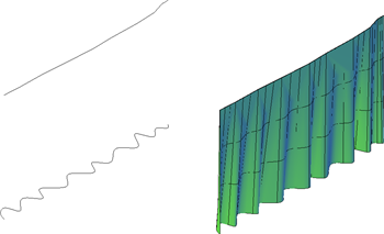
Loft profiles can be open or closed, planar or non-planar, and can also be edge subobjects. Use the mode option to select whether to create a surface or a solid.
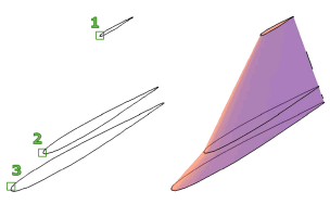
When creating surfaces, use SURFACEMODELINGMODE to control whether the surface is a NURBS surface or a procedural surface. Use SURFACEASSOCIATIVITY to control whether procedural surfaces are associative.
You can use the following objects and subobjects with LOFT:
|
Objects That Can Be Used as Cross Sections |
Objects That Can Be Used as a Loft Path |
Objects That Can Be Used as Guides |
|---|---|---|
|
2D polyline |
Spline |
2D spline |
| 2D solid | ||
|
2D spline |
Helix |
3D spline |
|
Arc |
Arc |
Arc |
|
Circle |
Circle |
2D polyline
Note:
2D polylines can be used as guides if they contain only 1 segment. |
| Edge sub-objects | Edge subobjects | Edge subobjects |
|
Ellipse |
Ellipse |
3D polyline |
|
Elliptical arc |
Elliptical arc |
Elliptical arc |
| Helix |
2D polyline |
|
|
Line |
Line |
Line |
| Planar or non-planar face of solid | ||
| Planar or non-planar surface | ||
|
Points (first and last cross section only) |
3D polyline |
|
| Region | ||
| Trace |
To automatically delete the cross sections, guides, and paths, use DELOBJ. If surface associativity is on, DELOBJ is ignored and the originating geometry is not deleted.
List of Prompts
The following prompts are displayed.
- Cross Sections in Lofting Order
-
Specifies open or closed curves in the order in which the surface or solid will pass through them.
- Point
-
If you select the Point option, you must also select a closed curve.
- Join Multiple Curves
-
Joins multiple, end-to-end curves as one cross section.
- Mode
-
Controls whether the lofted object is a solid or a surface.
- Options
- Continuity
-
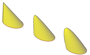
This option only displays if the LOFTNORMALS system variable is set to 1 (smooth fit). Specifies whether the continuity is G0, G1, or G2 where the surfaces meet.
- Bulge Magnitude
-
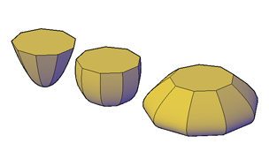
This option only displays if the LOFTNORMALS system variable is set to 1 (smooth fit). Specifies a bulge magnitude value for objects that have a continuity of G1 or G2.
Guides
-
Specifies guide curves that control the shape of the lofted solid or surface. You can use guide curves to control how points are matched up on corresponding cross sections to prevent undesired results, such as wrinkles in the resulting solid or surface.
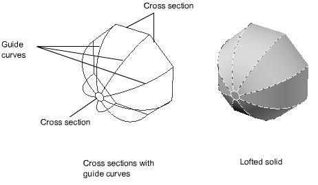
- Intersects each cross section
- Starts on the first cross section
- Ends on the last cross section
Select any number of guide curves for the lofted surface or solid and press Enter.
Path
-
Specifies a single path for the lofted solid or surface.
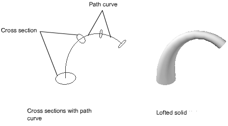
The path curve must intersect all planes of the cross sections.
Cross Sections Only
-
Creates lofted objects without using guides or paths.
Settings
-
Displays the Loft Settings dialog box.