When you connect one object to another at different elevations or slopes, or connect objects whose centerlines are not aligned, the software can generate routing solutions with different combinations of fittings or joints. You can step through a preview of the generated routing solutions and accept the layout that satisfies your design requirements on the command line.

Command line
If none of the routing solutions presented on the command line are satisfactory, select one that most closely matches your requirements and then use grips to modify the layout.
The following example describes how routing solutions work when connecting a pipeline to a chiller. The pipeline is on a different elevation, and the end of the pipeline is not in line with the chiller connection. You select the last pipe segment, and click ![]() (Add grip) on the open end. You move the cursor to the chiller connection, and then click the pipe end connector.
(Add grip) on the open end. You move the cursor to the chiller connection, and then click the pipe end connector.
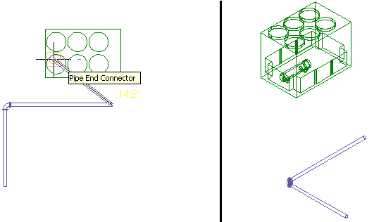
The second viewport is set to an isometric view to preview routing solutions
In this example, 2 routing solutions are generated. Each routing solution is based on the fittings in the current routing preference. The angles are determined by the allowable angles in the selected elbow. You preview the routing solutions and select the most suitable layout.
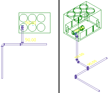

First routing solution