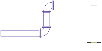
In new pipe runs, you lay out the pipe geometry by specifying points in the drawing. You control how the pipes, fittings, and transitions are automatically inserted based on what is specified in the current routing preference. The following examples illustrate how auto layout works.


The user moves the cursor at a 90 degree angle to the pipe segment.
Various AutoCAD MEP 2022 toolset tools work with auto layout in pipe runs. For example, you can specify an angle using the compass. The angles configured in the elbow content determine the available auto-layout angles. Tracking lines align a component with another object or line. Object snaps connect to pipe objects or to a geometric point on an object or line.
Auto layout can generate sloped piping layout solutions for gravity-based pipe systems based on points in the drawing. For example, auto layout determines whether to insert a transition. If so, the angle of deflection is equally distributed between female connectors on a fitting that supports sloped piping. If you set the slope value on the Properties palette to 10 (degrees), and the pipe object has 2 female connectors, then each connector can have an angle of deflection of 5 degrees each. The value cannot exceed the stored angle of deflection (AoD) value on the part.