A rise/drop style specifies the symbols to use in 2-line and 1-line displays of rise conditions and drop conditions on segments and fittings.
You can define the following types of rise/drop styles: duct, pipe, cable tray, conduit, and plumbing. Duct rise/drop styles allow you to specify symbols for different shapes: round, rectangular, and oval. You can also specify whether to show a rise or a drop symbol when duct or pipe runs underneath an MvPart, or when a vertical duct has an endcap.
To define a rise/drop style
- If necessary, create the AutoCAD blocks to be used by the symbols in the rise/drop style. For guidelines, see Rise/Drop Styles.
-
Click

 .
.
- In the left pane, expand the folder for the appropriate objects (for example, the Piping Objects folder).
- Right-click Rise Drop Styles, and click New.
- Enter a name for the new style, and press ENTER.
- Select the new style.
- For Description, enter a description of the style.
- If desired, attach notes or reference documents to the style.
- Click the Rise and Drop tab.
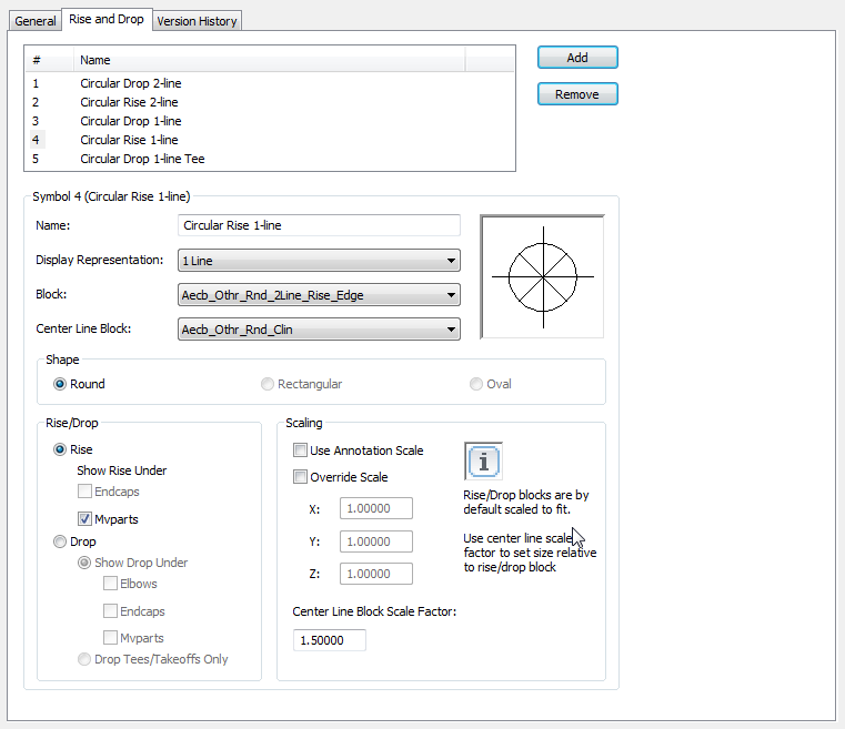
Rise and Drop tab for a sample pipe rise/drop style
The top pane lists the default symbols to be created by the software for the new style. The properties for the currently selected symbol are shown below.
Attention:To simplify the process of configuring the symbols in a rise/drop style, it is recommended that you reconfigure as necessary—but do not remove—the default symbols. They make up the minimal set of rise symbols and drop symbols needed for all possible rise conditions and drop conditions in 2-line and 1-line displays. Without this minimal set, the style is not valid. For example, a pipe rise/drop style is not valid without the following symbols: 2-line rise, 2-line drop, 1-line rise, 1-line drop, and 1-line drop for tees and takeoffs only. Similarly, a plumbing rise/drop style is not valid without the following symbols: rise, drop.
- Select the number of a symbol to configure.
- For Name, enter a descriptive name that identifies the context in which the symbol will be used.
- For Display Representation, select the display representation in which the symbol will be displayed.
For a 2-line display, select a Plan or 2 Line display representation. For a 1-line display, select a 1 Line display representation.
- For Block, select the AutoCAD block (defined in the current drawing) that represents the symbol.
- If you want to display center lines on the symbol, for Center Line Block, select the AutoCAD block (defined in the current drawing) that represents the center lines.
A preview image of the symbol, defined by the selected blocks, displays on the right.
- If the rise/drop style is for ducts and duct fittings, under Shape, select the shape to apply to the symbol.
- Under Rise/Drop, choose either a Rise or a Drop option as described next:
If you select... Then the current drawing shows the... Show Rise Under MvParts rise symbol under an MvPart. Show Rise Under Endcaps rise symbol under an endcap. Show Drop Under Elbows drop symbol under an elbow with a connector in the down direction. Show Drop Under Endcaps drop symbol under an endcap. Show Drop Under MvParts drop symbol under an MvPart. Drop Tees/Takeoffs Only drop symbol only used to represent tees and takeoffs in 1-line displays Note: In 1-line displays that do not show the contour of an object, this identifies the appropriate symbol to use for tees and takeoffs in drop conditions. - Under Scaling, specify how to scale the symbol block:
If you want to scale the symbol block ... Then ... to the actual diameter (in 2-line displays) or the nominal diameter (in 1-line displays) of the segment or fitting clear Use Annotation Scale, and clear Override Scale. using the current annotation scale select Use Annotation Scale. This scales the block to the annotation plot size (specified on the Scale tab of the Drawing Setup dialog) multiplied by the scale factor for the current annotation scale. Note: The Use Annotation Scale setting for the symbol, not the Annotative property in the selected symbol block definition, determines whether the symbol is annotative (scales according to the annotation scale).using a scale factor that you specify select Override Scale, and for each coordinate direction (X, Y, and Z), enter the scale factor to use to scale the block. Note: If you select both this and Use Annotation Scale, the block is scaled using the scale factors you enter, and then the result is multiplied by the scale factor for the current annotation scale.When the symbol block is inserted in a drawing, it is first scaled so that its extents are one unit (for example, one inch or one millimeter); it is then rescaled based on your selection here.
- If you want to scale the center line block relative to the symbol block, for Center Line Block Scale Factor, enter the scale factor.
For example, to scale the center line block to the same size as the symbol block, enter 1. To scale it so it is 50% larger than the scaled symbol block, enter 1.5.
Tip: The preview image updates dynamically to assist you in specifying the desired scale factor for the center line block. - Select the next symbol, and configure it using the same process.
- If you want to add additional rise graphics or drop graphics, click Add, and configure an additional symbol to be displayed in a specific rise condition or drop condition.
- If you want to delete a symbol, click Remove.