In a drawing, rise symbols and drop symbols are used to represent vertically-oriented segments and fittings, and to indicate corresponding rises and drops in elevation in the layout. In AutoCAD MEP 2022 toolset , a rise condition exists if an unconnected end on a vertically oriented segment or fitting is visible in the current view. If the segment or fitting is vertically oriented but does not have a visible, unconnected end, a drop condition exists. Rise/drop styles let you specify the symbols to use in both rise and drop conditions.
A rise/drop style defines not only the symbols to use, but also the 2-line and 1-line displays in which to use them. For duct rise/drop styles, you can also specify different symbols for different shapes of ducts and fittings: round, rectangular, and oval.
Rise/drop styles are used in the orthographic views: Top, Bottom, Left, Right, Front, and Back.
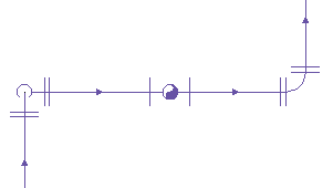
1-line display of a pipe run
You can specify a rise/drop style for each system in a drawing. For example, you can specify one style for a supply system and a different style for a return system. This helps to visually differentiate the systems, as shown in the following plan view of a supply run and a return run, both with vertical components.

Supply duct run
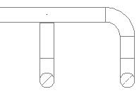
Return duct run
Creating Blocks for Rise Symbols and Drop Symbols
Before you define a rise/drop style, you need to create the AutoCAD blocks that will represent the rise symbols and drop symbols. Keep the following guidelines in mind as you create the blocks:
- Rise/drop styles (and, therefore, the associated blocks) must exist in the current drawing if they are to be used. This means you must either create the blocks and styles directly in your drawing templates (which typically are used to create new drawings), or you must create them in a content library (a DWG file), and then copy them to your drawing templates.
- Before you create a block for a rise symbol, set the current color, linetype, and lineweight to ByBlock. When the block is inserted in a drawing, the values for these properties in the Rise Drop display component will be used.
- Before you create a block for a drop symbol, set the current color, linetype, and lineweight to the desired values for the symbol. When the block is inserted in a drawing, the values for these properties will be retrieved from the block definition, and any values for these properties in the Rise Drop display component will be ignored. Note: Configuring the blocks for rise symbols and drop symbols as just described allows you to specify different values for the display properties of each. You control the visibility of both using the Visibility setting for the Rise Drop display component.
- You can create a block at any size. When it is inserted in a drawing, the block is scaled so that its extents are one unit (for example, one inch or one millimeter); it is then rescaled according to the specifications in the rise/drop style.
- To ensure that the symbol is displayed in the correct location relative to a layout, specify the center of the symbol as the base point of the block.
- Create oval blocks as flat ovals, using the blocks provided with the software as a guide.