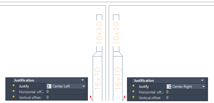
Justification applies to the orientation of a segment relative to the draw direction and the centerline of the object. Justification is stored on the following 3D segment-based MEP objects:
- Duct (rectangular, oval, round)
- Cable tray (rectangular)
- Conduit (round)
- Pipe (round)
The default justification is the centerline of the object, with no horizontal or vertical offsets. The centerline of the resulting segments and fittings is placed along the points you specify as you draw runs. The elevation specifies the height location for vertical justification.
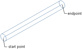
Justification along centerline
The following justification settings are available on the Properties palette:
- Top Left, Center, Right
- Middle Left, Center, Right
- Bottom Left, Center, Right
You can also enter a distance for horizontal or vertical offsets.
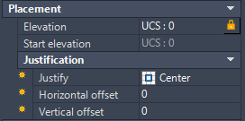
Justification on the Properties palette
Justification is based on the draw direction from connector 1 (start point) to connector 2 (endpoint), as shown:

Draw direction
The following example contrasts Top Left and Top Right justification of a duct object. Notice that the draw direction, as shown by arrows, determines how justification is represented in the drawing.
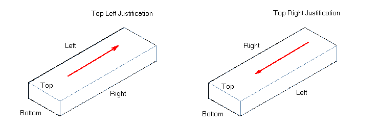
Arrows show the draw direction from the start to the endpoint
If you start drawing from a fitting that is connected to a segment, the justification of the connected segment is applied to the new segment. If no segment is connected, the last used justification is used.
You can use the AutoCAD command to mirror 2 objects on either side of a wall. In this case, justification is adjusted based on the object's orientation to the wall. The next 2 examples illustrate mirrored ducts. The first example shows the MIRROR command applied to the first duct.
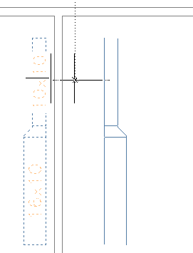
The second example shows the mirrored duct placed on the other side of the wall. Notice the difference in justification of the 2 duct objects based on their orientation along the wall, Top Left versus Top Right.
