When you add a device to a drawing, you need to configure its connectors using the Electrical Properties worksheet. Typically, devices have a single electrical connector.
You can configure an electrical connector using either of the following methods:
- Assign the connector to a circuit. If you know the circuit, you can select it. Otherwise, you can make panel and connector property selections to filter the list of available circuits, and then select one.
Once you select a circuit, the System value is no longer editable. If the system type of the connector is Power and Lighting, then the values for Voltage and for Number of poles are not editable. This prevents changes that do not agree with the selected circuit. You can then configure the connector properties that remain editable.
As you add devices with connectors that are assigned to a circuit, the circuit is updated and evaluated for overloads based on the load and load category of the connectors. In the circuiting preferences, you can specify whether the software warns you of overloads, so you can decide whether to proceed and add the devices. If you overload a circuit, you are not notified of the overload again during the drawing session.
- Configure the connector properties, but do not assign the connector to a circuit. Later, after you identify the circuit to use, you can assign the circuit.
Note: If the style of the device does not allow the override of a connector property value, that property is not editable even when no circuit has been assigned. For information about allowing and preventing overrides, see Configuring Connectors for Device and Panel Styles.
- Start the add command by doing one of the following:
- Click
 .
.
- Open a device tool palettedeviceadd, and select a tool.
- Enter DEVICEADD.
- In the Styles Browser palette, set Object Type Device. Search, import (
 ), and start (
 ) the command.
- Click
- On the Properties palette, expand Advanced, expand Circuits, and click
 Electrical Properties.
Note: You can apply these settings later by selecting a device in the drawing and clicking
.
Electrical Properties.
Note: You can apply these settings later by selecting a device in the drawing and clicking
.
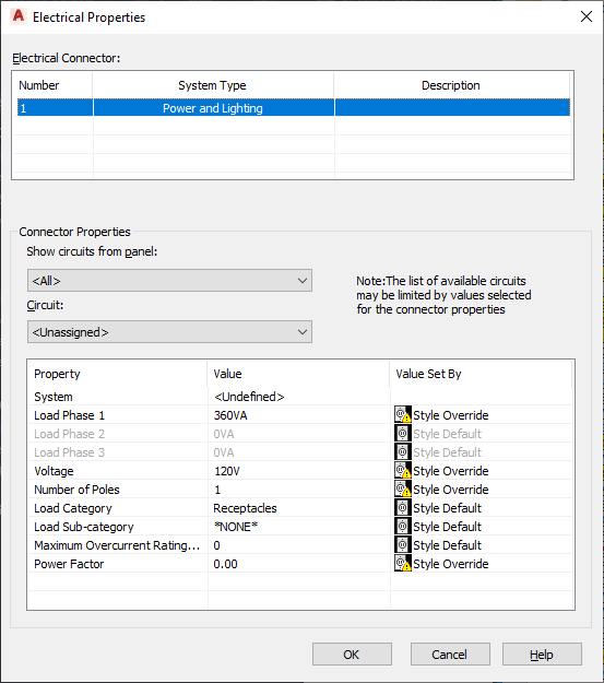
The Electrical Properties worksheet lists the connectors on the device and shows the system type and description for each connector. These attributes of the device are determined by the device style, and, to change them, you must modify the connectors in the style.
- Under Electrical Connectors, select a connector to configure.
The properties of the selected connector are displayed under Connector Properties.
- If necessary, you can filter the list of available circuits:
If you want to select from the circuits… then… on a specific panel for Show circuits from panel, select the panel. that are not assigned to a panel for Show circuits from panel, select Unassigned. with a specific system for System, select the system. with a specific number of poles for Number of Poles, select the number. with a specific voltage for Voltage, select or enter the voltage. Detailed descriptions of the connector properties are described later in this procedure.
Note: The circuits available for Circuit are the circuits in the current drawing, or in the electrical project database file, if one is specified for the current drawing. The circuits available are those that match the values you have specified for the connector properties, and have either a system type of General or the same system type as the connector. Beside each circuit name, the current load on the circuit is displayed. The load is the total load on the circuit across all applicable drawings, including the electrical project database file. - For Circuit, select the circuit.
- Under Value, specify values for the connector properties.
Connector Property Description System The system of the connector. If the system type of the connector is General, you can select from all of the electrical systems defined in the drawing. Otherwise, you can select from systems with the same system type (Power and Lighting, or Other). Note: While the system assigned to the device determines its display properties, the system assigned to the connector on a device determines the connections that can be made to the connector. If the system type of the connector’s system is Power and Lighting or Other, you can only connect objects of the same system type to the connector. If the system type is General, you can connect objects of any system type to the connector.Load Phase 1 Load Phase 2 Load Phase 3 The load on the connector. Applies only to connectors whose system type is Power and Lighting. If the Number of Poles is <Undefined> or 1, only Load Phase 1 is editable. If Number of Poles is 2, then Load Phase 1 and Load Phase 2 are editable. If Number of Poles is 3 or <By Circuit>, then Load Phase 1, Load Phase 2, and Load Phase 3 are editable.
You can enter a value. Otherwise, the value in the style is used and shown.
Voltage The voltage on the connector. Applies only to connectors whose system type is Power and Lighting. You can do one of the following:
- enter a voltage
- select from the voltages defined in the drawing that are valid for the currently specified number of poles
- select By Circuit to retrieve the value from the circuit when it is assigned
Number of poles The number of poles on the connector: 1, 2, or 3. Applies only to connectors whose system type is Power and Lighting. You can select a number, or you can select By Circuit to retrieve the value from the circuit when it is assigned.
Load Category The load category of the connector. Applies only to connectors whose system type is Power and Lighting. You can select from the load categories defined in the drawing.
Load Sub-category The load sub-category of the connector. You can select Motor. Maximum Overcurrent Rating (amps) Reserved for future use. Power Factor Reserved for future use. As you specify values for the connector properties, the information in the Value Set By column changes accordingly:
If… then Value Set By is… the value of the property matches the value specified in the device style Style Default the value of the property does not match the value specified in the device style Style Override there is no value specified in the device style empty the value of the property is By Circuit in the device style or in the currently selected connector Circuit
To configure the electrical connectors of a device
Optionally assign the connector to a circuit
Specify the connector properties