After attaching a referenced drawing (xref) of the architectural plan to your drawing, typically you continue by placing devices and panels in the layout. You can place devices and then connect them with wires. You can also insert a device onto a wire, in which case the device breaks into the wire and creates 2 wires.
When you add a device to your drawing, you can assign the device to a circuit, or you can leave the circuit unassigned until you know the circuit to use. This ability means you can create circuits and connect them to devices at any time during the design process.
- In the Electrical workspace, start the add command by doing one of the following:
- Click
 .
.

- Open a device tool palette, and select a tool.
If necessary, scroll to display the tool. Because tools contain preconfigured properties for the objects they create, you might not need or be able to specify some of the device properties referenced in this procedure.
- In the Styles Browser palette, select Object Type Device. You can search, import (
 ), and add a device (
 ).
).
- Enter deviceadd.
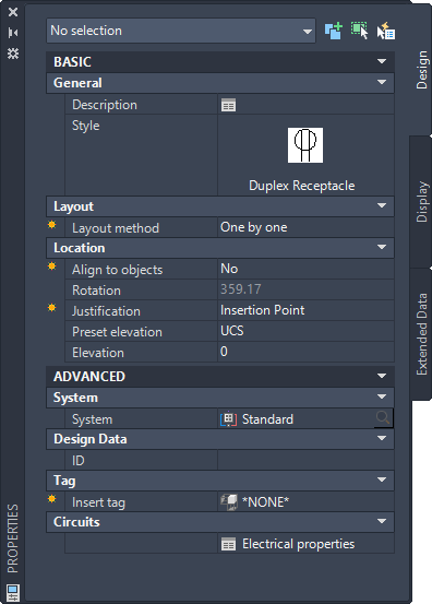
Note: On the Properties palette, indicates a property is available only when you are adding devices, not when you are modifying them.
- Click
- On the Properties palette, if necessary, double-click on the device display to open the style selector dialog box.
- For Description, click
 , enter a description of the device, and click OK.
- If you selected One by One for Layout Method, expand Location, and for Align to objects, specify how you want to align the devices:
If you want to… then… snap to an object using object snaps and have the software align the device perpendicular to the object select Yes. The software can align the device perpendicular to a wall, ceiling grid, space boundary, line, polyline, spline, arc, or circle in the current drawing or in an xref.
Note: If you have difficulty snapping and aligning to an object, zoom to the area or modify the size of the AutoSnap aperture as needed. The aperture size determines how close to a snap point you can be before the magnet locks the aperture box to the snap point. You can modify the size on the Drafting tab of the Options dialog box.manually align the device select No. Note: If you select Yes for Align to objects, the software inserts the device using the insertion point of the underlying block and rotates it as needed to align it perpendicular to the object to which you snap. As a result, you cannot specify a value for Justification on the Properties palette, or a value for Rotation on the command line. If you selected Distance around space or Quantity around space for Layout method, Align to objects is automatically set to Yes. - For Justification, select the point on the device to use as the insertion point.
You can select either the insertion point of the view block that represents the device, or one of 9 other points on the device, such as Top Left or Middle Center.
- Specify an elevation by doing one of the following:
- For Preset Elevation, select a defined elevation.
- For Elevation, enter an elevation.
Because devices have 2D views and many have 3D views assigned to them, the insertion point of devices should be specified as 0. The elevation property of the device (not the insertion point) should be used to assign the 3D view to the correct elevation. Follow these simple rules:
- The Z-value of Connectors should always be defined as 0.
- The Insertion point Z-value of device shall be 0.
- To set the elevation of the device to anything other than 0, use the Elevation property of the device on the Properties palette. This setting defines the 3D offset of the device from the current UCS. The object will display at the set elevation when viewing it in a 3D or Iso view.
The difference in the elevation of the devices, the wires, and the panel for a circuit is used to calculate the circuit length. Note that the circuit length can only be calculated if the panel and all of the devices on the circuit are in the current drawing.
- Expand Advanced, expand System, and for System, select the system to which the device belongs.
Note: The system assigned to the device determines its display properties, and the system assigned to an electrical connector on a device determines the connections that can be made to the connector. For more information about connectors, see Configuring the Electrical Connectors of a Device. For more information about systems, see Configuring Electrical System Definitions and Working with Systems.
- Expand Design Data, and for ID, enter an ID for the device.
The ID is an optional number that you can assign.
- Expand Tag, and for Insert Tag, select the tag to anchor to the object.
The list of tags includes the tags in the current drawing and, if specified, the tag specified in the tool you selected.
A tag is a symbol that can display the data in a property set that is attached to the object. A property set is a user-defined group of related properties, such as a part number or a manufacturer’s name, which you can specify in the properties of a tag tool or manually attach to an object using the Extended Data tab of the Properties palette. You use property sets and tags to annotate drawings and create schedules for construction documents.
Tip: Instead of manually adding tags and property sets to devices one-by-one using the Properties palette, you can create device tools that automatically add them to devices when the devices are inserted. For more information, see Creating Tools for Devices, Panels, and Wires. - Expand Advanced, expand Circuits, and click
Electrical Properties.
Note: You can edit Electrical Properties later by selecting a device in the drawing and clicking
.

- On the Electrical Properties worksheet, configure the electrical connectors, as explained in Configuring the Electrical Connectors of a Device.
- If you selected Quantity around space or Distance around space for Layout method, insert the devices as follows:
- In the drawing, move the cursor to the location for the first device. This must be a point on a space boundary.
- Examine the preview of the device layout, and, if necessary, move the cursor to a different location.
- Click to insert the devices.
- If you selected One by One for Layout method and Yes for Align to objects, insert the devices as follows:
- If you want to insert the device into a wire, enter w (wire), and select the wire. Otherwise, proceed to the next step.
- Use object snaps to snap to an object (such as a wall) at the desired insertion point, and click to insert the device.
- Repeat the previous steps to add additional devices with the same properties.
- If you selected One by One for Layout method and No for Align to objects, insert the devices as follows:
- If you want to insert the device into a wire, enter w (wire), select the wire, and move the device along the wire to the desired location. Otherwise, proceed to the next step.
- Click to specify the insertion point.
- Rotate the device by moving the cursor or entering the number of degrees on the command line, and click to insert the device. Alternatively, you can press Enter to accept the default rotation, and then click.
- Repeat the previous steps to add additional devices with the same properties.
- On the Properties palette, modify the device properties and then insert additional devices, or press Enter to end the add command.
Note: If you are using the electrical project database file, and two or more electrical drawings are open, you can update each drawing to include the most current circuit information by reloading the electrical project database in each open drawing. For example, if you add lighting devices to a circuit in the electrical project database, and a power drawing is open and using circuits on the same panel, you can reload the electrical project database in the power drawing to have current circuit information.
To add devices
Specify general properties
Specify location properties
Specify advanced properties
Specify connector properties
Insert the devices