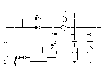
A schematic drawing is a two-dimensional (2D), not-to-scale flow diagram that shows the logic and operation of a building system. You draft a schematic or single-line diagram of your system to use as a basis for your complete design layout, or to create plumbing riser diagrams or details associated with your design. Generally, drafting a schematic diagram is one of the first steps in the building systems design process; however, not every project requires a schematic diagram.
Schematic diagrams are useful, for example, for representing how air moves through a building’s heating system or how electrical power, or hot and cold water, are carried through a building. They can also show relationships between equipment and other components in a system. For example, a mechanical schematic diagram can identify the types of equipment required for a system and show the connecting duct or pipe.

Sample mechanical schematic diagram
You create a schematic diagram by connecting symbols with lines to show the basic function of the building system. The diagram typically includes little information about individual parts.
You can create schematic diagrams in an orthographic or an isometric view direction. The orthographic plan view drawing is the more common type of schematic diagram. The isometric diagram is typically used for a complex layout that requires the representation of additional details.
- Create elevations or sections based on the drawing
- Use the duct sizing tools or plumbing sizing tools provided with AutoCAD MEP 2022 toolset. To use these tools, create the system using ducts and duct fittings, or plumbing lines and plumbing fittings.