- Begin a new parametric part, specify its part configuration, and add the default work planes (ZX plane, YZ plane, and XY plane).
- In the part browser, click
 .
. 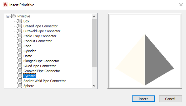
Insert Primitive dialog box
- In the Insert Primitive dialog box, select the primitive to add to your part model, and click Insert.
- Select the work plane on your part to which to attach the primitive:
If you want to… then… attach the primitive to an existing work plane in the modeling area, select the work plane. attach the primitive to the face of an existing primitive or modifier press Enter, and, in the modeling area, select the face of the primitive or modifier. Note: This creates a reference work plane on the selected face and attaches the primitive to the new plane.To facilitate the selection of a plane or face, the software highlights the plane or face when you move the cursor over it.
- Select the work plane on the primitive that you want to align with the work plane selected in the previous step.
Most of the primitives included with the software include multiple work planes. To select the current plane, do nothing. To cycle through the planes on the primitive and make another plane current, enter n (next), and press Enter. As you cycle through the planes, notice how the software repositions the primitive in the modeling area so the current plane on the primitive aligns with the selected plane on your part.
Note: This step aligns the centers of the selected planes so they match. As a result, the placement of the primitive on the plane on your part depends on the location of the primitive on its own plane. The primitives included in the software were created in the center of a horizontal plane. - If desired, change the orientation of the primitive:
If you want to… then… flip the primitive so it is positioned on the other side of the plane to which it is being added enter f (flip plane), and press Enter. rotate the primitive around the center of the plane to which it is being added enter r (rotate). Move the cursor and click to specify the angle change. Alternatively, you can enter the angle change on the command line and press Enter. insert a mirror copy of the primitive instead enter m (mirror), and press Enter. - When you have positioned and oriented the primitive as desired, press Enter.
The software copies all of the modeling features in the primitive into your custom part. If the units in the drawing that defines the primitive do not match the units in your part drawing, the software also converts the units appropriately. You can now work with the part model as if you had created all of the features manually.
In the model parameters of your part, the descriptions of the parameters that were derived from a primitive include the name of the primitive. This makes it easier for you to differentiate parameters when you have added multiple primitives, or a mixture of primitives and manually added features, to the part model.
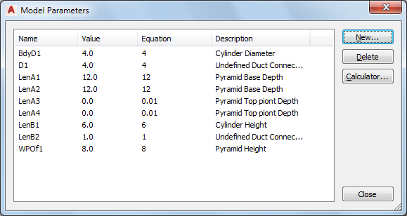
Model Parameters dialog box