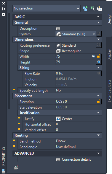
Add the basic properties of a duct using the properties palette.
By default, Basic properties are displayed in the Duct Properties palette.
| General | Action | Selections |
|---|---|---|
|
Description |
Describes the duct part (optional). |
|
|
System |
Selects a system definition for the duct object in the current drawing. |
Standard (default); selections derived from the catalog |
|
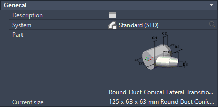
***Part |
Click the image next to part to open the Select a Part dialog box. | |
| ***Current Size |
Choose one of the sizes proposed in the drop-down menu. All sizes are standardized. |
|
 General User Interface for Duct fittings |
| Dimensions | Action | Selections |
|---|---|---|
| Routing preference | Selects a routing preference for the duct object in the current drawing. | Standard (default); selections derived from the catalog |
| Shape | Specifies the shape for the selected object. | Rectangular (default); thereafter last used shape |
| Size | Selects a size within the range specified in the current routing preference. There are different default size parameters, depending on the selected shape.
|
Last used value selected |
| Calculate Size | Calculates the sizes of the duct based on the Flow Rate, Friction, Roughness and Density. If a rectangular or oval shape is selected, one size has to be fixed to calculate the other one. Note: For more information, see Duct Size Calculator.
|
|
|
Size lock |
Prevents the size value from being changed. |
|
| ***Connections | Customize the sizes of the fitting you want to add. | |
| *Flow Rate | Flow Rate is read from MvParts that are connected to the Duct Run or can be entered. | 0 (default). Flow Rate will be automatically refreshed if the Duct is connected to a MvPart. |
| *Friction | Shows the value for friction of the selected object based on the definition in the Duct System Definitions section in the Style Manager (Read-only). | |
| *Velocity | Shows the value for velocity of the selected object based on the definition in the Duct System Definitions section in the Style Manager (Read-only). | |
|
Cut Length |
If Yes is specified, then Cut Length lets you specify a dimension. Selecting No hides the Cut Length property. |
No (default) |
| Placement | Action | Selections |
|---|---|---|
|
Elevation |
Specifies a Z value (elevation) above or below the XY plane of the current user coordinate system (UCS). |
0 (default), thereafter last used elevation |
|
Elevation lock |
Prevents objects of one elevation from snapping to objects of another elevation. |
|
|
Start elevation |
Specifies an elevation for connector 1 on the duct object. Start elevation is the same value as Elevation. |
0 (default) |
| Justification | Action | Selections |
|---|---|---|
|
Justify |
Orientates the justification of the duct object. |
|
|
Horizontal offset |
Specifies a placement offset in the horizontal direction from the insertion point. |
0 (default); thereafter last used value |
|
Vertical offset |
Specifies a placement offset in the vertical direction from the insertion point. |
0 (default); thereafter last used value |
| Routing | Action | Selections |
|---|---|---|
|
*Bend method |
Select the desired Bend method. Choose either Elbow, Offset or Transition Offset. |
|
|
*Bend method lock |
Prevents the bend method from being changed. If you do not lock the offset or transition - offset bend method, then the setting reverts to elbow after one instance of the selected bend method is inserted in the duct run. Note: Appears only if the offset or transition - offset is chosen.
|
|
|
*Bend angle |
Specifies the angle to constrain the routing in the duct run. |
The bend angle varies, depending on the values that are defined in the catalog content. |
|
*Bend angle lock |
Prevents the bend angle from being changed. The Bend angle lock button appears only for user defined angles. |
|
|
**Segment |
Specifies the layout method for the flexible duct. |
|
|
**Radius factor |
If Line is selected for Segment, radius factor lets you specify a radius value. |
|
|
*Branch fitting |
Specifies the way to connect ducts. |
|