A part template is a fully configured and fully dimensioned parametric part that has a basic model but does not have any part sizes. The imperial and metric catalogs in AutoCAD MEP 2022 toolset include part templates for several, commonly used MvParts (for example, air terminals and pumps) and fittings. Using the Parametric Part Wizard, you can quickly create a new parametric part with custom sizes based on a part template.
Creating parametric parts using the part wizard is recommended when you require only a basic model to represent the part. The wizard is particularly useful for creating parts with one or a few sizes in real time as you design a building system.
If your custom part requires a more complex model than a part template provides, or if it must be block-based instead of parametric, create the part using the Content Builder instead. You can also use the Catalog Editor to copy parts and add custom part sizes to the copies.
To create a parametric part using the Parametric Part Wizard
- Click Home tab
 Build panelTools drop-downParametric Part Wizard..
-
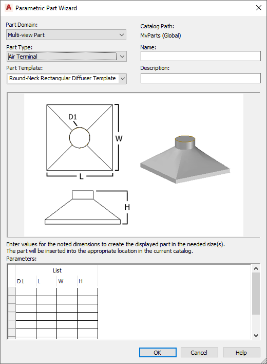
Parametric Part Wizard
- For Part Domain, select the domain of the catalog that contains the part template you want to use.
You specify a catalog for a domain in the Options dialog box. For more information, see Specifying Default Part Catalogs and Style-Based Content Locations.
- For Part Type, select the part type of the template whose shape resembles the part you want to create.
- For Part Template, select the name of the part template whose shape resembles the part you want to create. Note: The lists of choices for Part Domain, for Part Type, and for Part Template are filtered to include only those for which there are defined part templates.
- For Name, enter a name for the new part.
The part name is used to name the XML file that defines the part. It is also displayed when the part is opened in Content Builder or Catalog Editor.
- For Description, enter a description for the new part.
Users select parts by description in add dialogs and modify dialogs. The description is also used to create the names of the part sizes.
- Under Parameters, enter values for the size parameters shown in the part image.
The values are used to create the list of part sizes. To enter a value in a cell, double-click the cell, and then enter the value. To access the Copy, Paste, and Clear commands, right-click the cell.
Note: In the part wizard, you enter the values for the size parameters differently depending on how they are stored in the software:- In a table of values where all of the size parameters (columns) must have the same number of values, and a row across the columns defines a single part size
- In lists of values where the values in the lists are used in all possible combinations to define multiple part sizes

Example of Parameters showing values for custom round-neck diffuser
Use the prompts provided by the software to guide you in entering the data. For more information about the different types of data storage for size parameters, see Understanding Part Sizes.
- Click OK to create the part in the specified part sizes.
The software adds the part to the current catalog, more specifically, to the chapter that corresponds to the part type that you selected. The Add Multi-view Parts dialog box is displayed to add the new part to your drawing, if desired.
If necessary, you can also modify the part’s data and add custom data using the Catalog Editor or Content Builder. For example, you can modify the formula used to create the names of part sizes.