The Format panel of the Power Dimensioning contextual tab contains several options to help modify dimension geometry. The Edit Geometry button displays a dialog box, that shows a graphical representation of the various components of a dimension. The graphical representation is context sensitive and changes depending on the selected dimension.
 |
 |
 |
 |
 |
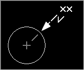 |
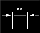
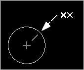
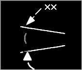
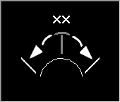
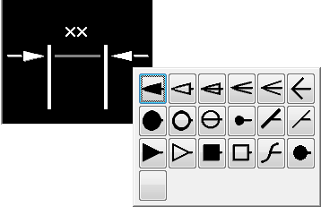
You can click a component in the graphical representation to turn its visibility on or off. Components that have their visibility turned off are made dim in the preview. When you click on an arrowhead, AutoCAD Mechanical toolset displays a list of arrowheads you can select from.
The Format slideout panel contains two buttons that apply to radial dimensions. These buttons control the arrowhead position and the usage of leader lines for dimension text, in radial dimensions. This in combination with the drop-down list to the left of these buttons let you control the visibility of leader lines and position of dimension text.

The drop-down lists also control how to display dimension text, if the gap between extension lines is not large enough to contain the arrows and dimension text.
In addition to the Power Dimensioning contextual tab, you can select a dimension and right-click to access a menu containing several formatting options.
If the Power Dimensioning contextual tab is turned off (by turning the ribbon off or setting the AMPOWERDIMEDITOR system variable to 0), you must use a combination of the AMPOWERDIM command and the AMDIMFORMAT command to access these options.