We recommend that you use mechanical structure to organize your drawing instead of layer groups. Mechanical structure provides a better and more comprehensive set of tools to manage drawing components than layer groups. Layer groups continue to remain in the product only for compatibility reasons.
AutoCAD Mechanical toolset provides the ability to create multiple sets of mechanical layers. Each set is referred to as a layer group. Once you create a layer group and set it to “current,” AutoCAD Mechanical toolset commands draw objects on the mechanical layers within that layer group.
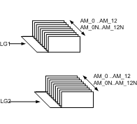
The working layers (AM_0 through AM_12) and the standard part layers (AM_0N through AM_12N) are replicated in each layer group. The special layers AM_BOR (used for drawing borders), AM_PAREF (used for part references), AM_CL (used for construction lines), AM_VIEW (used for viewports), and AM_INV (used for invisible lines) are not replicated. The illustration above shows two layer groups LG1 and LG2, which contain two separate sets of mechanical layers. Since AutoCAD does not allow duplicate layer names, if you inspect a mechanical layer using the AutoCAD LAYER command, you will see that the name of the layer is prefixed with the layer group name. For example, the layer AM_0, that belongs to the layer group LG1 is shown as LG1-AM_0.When you have not explicitly created any layer groups, you are assumed to be working on a hypothetical layer group that is referred to as the Base Layer Group.
You can use layer groups to associate or relate items within a drawing. For example, in a drawing containing the design of an engine, you can place all views of the shaft in the “Shaft” layer group and all views of the gearbox housing in the “Gearbox Housing” layer group. You can apply visibility enhancements to individual layer groups within the drawing, highlighting the shaft within the gear box assembly, for example.
With mechanical layer groups, you can:
- Move or copy objects from one layer group to another.
- Work globally with individual layers that are part of a layer group. For example, you can turn off crosshatching regardless of the layer group on which you created it.
- Set a color for the layer group, and then override color of individual layers by the layer group color.
- Lock and freeze layer groups to simplify design work.
- Easily assemble or stack individual layer groups.