A reference component is an instance of a mechanical structure component that has been placed in a drawing to add context to a design or for visual enhancement.
Reference components are excluded from the bill of materials (BOM).
For example, consider a drawing of a die, which also shows the part that the die produces. If a BOM is created for the die, the part must not be listed in it, since the part is shown only to add context to the design. Setting the part to be a reference component eliminates it from the BOM.
When a component is set as a reference component, the mechanical browser adds the reference flag (an icon of a book) to the component icon ( ![]() ).
).
In AutoCAD Mechanical toolset, you can exclude a component from the parts list, using the Properties dialog box. Components excluded from parts lists in this manner are excluded from the parts list only and continue to exist in the BOM. Reference components, on the other hand, are excluded from the BOM as well. There is no visual clue (on the mechanical browser) to differentiate a component that is excluded from the parts list from any other component.
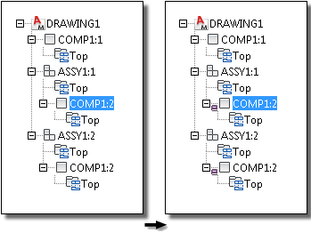
The reference component setting is instance-based. Only that instance is considered a reference component and all other instances continue to be normal components. However, if the instance occurs in another assembly in the same drawing, that instance is flagged as a reference component.
Example of a reference component

This example shows a drawing that contains two instances of the assembly ASSY1; ASSY1:1 and ASSY1:2. COMP1 occurs within ASSY1 (COMP1:2) and outside as well (COMP1:1). If you select COMP1:2 in ASSY1:1 and make it a reference component, COMP1:2 in ASSY1:2 also becomes a reference component. This is because the instance COMP1:2 occurs twice, once in ASSY1:1 and once in ASSY1:2. However, the instance COMP1:1 does not become a reference component.