AutoCAD Mechanical toolset provides many commands to create rectangular-shaped, closed polylines.
The AutoCAD RECTANG command also creates rectangles by specifying two opposite corners. However, depending on where you want to insert the rectangle, you may not always find this convenient. AutoCAD Mechanical toolset rectangle creation commands provide many other options to define rectangles.
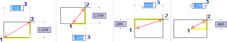
For example, if you press the SPACE bar after invoking the AMRECTANG command, the starting point changes. The cursor changes to show the current start point.
| Cursor | Meaning |
|---|---|
 |
Creates a rectangle using a corner as the starting point. |
 |
Creates a rectangle using the midpoint of the base as the starting point |
 |
Creates a rectangle using the midpoint of the height as the starting point. |
 |
Creates a rectangle using the center of the rectangle as the starting point. |
Once the command is invoked, you can choose to change the shape of the corners (fillet or chamfer). You can also control whether centerlines are drawn with the rectangle or not.
After that, specify the starting point that defines the rectangle. You can click in the drawing area to specify the second point. If dimension input is enabled, you can specify the second point by entering dimension values on the tooltip entry boxes near the cursor.
You can also define the rectangle using the area and either a length or a width. If the Chamfer or Fillet option is active, the area calculation takes them into consideration.
You can access all AutoCAD Mechanical toolset rectangle creation tools from the Rectangle button on the Home tab of the ribbon ( Find).