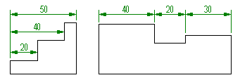
After placing a linear or angular dimension using AMPOWERDIM, you can use command line options to place subsequent dimensions as chain or baseline dimensions, within the same command session.

If you select the chain option, for each point you select, a chain dimension is created aligned to the previous (base) dimension.
Similarly, if you select the baseline option, for each point you select, a baseline dimension is created above or below the base dimension maintaining the correct dimension gap. Depending on the dimension you select as the base dimension, existing dimensions rearrange automatically. Each dimension line is offset from the previous one by the value in the DIMDLI system variable.
Instead of the AMPOWERDIM command, you can use the AMPOWERDIM_BAS command for baseline dimensions and the AMPOWERDIM_CHAIN command for chain dimensions. The AMPOWERDIM command uses command line options to select baseline and chain dimensions. The AMPOWERDIM_BAS and AMPOWERDIM_CHAIN commands skip the first selection step, but are identical to AMPOWERDIM in all other aspects.
You can also use the AMAUTODIM command to create chain and baseline dimensions. The AMAUTODIM command gives you the ability to create several dimensions simultaneously. You can dimension separate objects, as well as objects within blocks. You select the object to dimension, and then specify a point marking the origin of the first extension line. The command then creates dimensions from the origin to all vertices on the contour of the selected object. Distance snaps assist you to place the dimension at the appropriate distance from the object you are dimensioning. The DIMDLI system variable controls the spacing between dimensions. You can create dimensions for both axes in the same command session.
You can also convert baseline dimensions to chain and versa if you originally used the AMAUTODIM command create them.