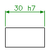
- In the drawing area, select the dimensions you want to edit. The Power Dimensioning Ribbon Contextual Tab displays.
- Click Power Dimensioning tab
 Fit/Tolerance panel
 Fit. Find
- To change the fit representation, click Power Dimensioning tab
 Fit/Tolerance panel
 Representation drop-down.
 - Click the icon corresponding to the desired representation.
- Click the Power Dimensioning tab
 Fit/Tolerance panel
 Symbol drop-down
 Fits Dialog box. Note: For some representations you must select symbols for the hole and shaft separately. In this case the Power Dimensioning tab
 Fit/Tolerance panel does not contain a Symbol drop-down. Instead it will contain 2 separate drop-down lists for the shaft and hole. In this case you must repeat step 6 for both, drop-down lists.
 - Select the required symbol and click OK.
- Press ESC.