Macro recommendation insights can help you reduce repetitive tasks, enforce CAD standards, and simplify workflows by executing multiple commands, along with expected options and values. These insights are based on the frequency in which you use specific sequences of commands.
Here are a couple examples of command sequences:
- COPY, ROTATE – COPY command used to copy objects followed by the ROTATE command used to rotate the previously copied objects.
- LAYER, DIMSTYLE, DIMLINEAR – LAYER command is used to set a current layer, followed by the setting a dimension style current. After that, the DIMLINEAR command is started to create a linear dimension on the specific layer and with the specific style.
Command sequences can be formatted into what are known as macros. AutoCAD supports two types of macros:
- Action Macros – Recorded using the Action Recorder and saved to an action macro (ACTM) file. When loaded, an action macro can be played back from the Action Recorder or by entering its name at the Command prompt.
- Command Macros – Defined in a customization (CUIx) file with the Customize User Interface (CUI) Editor and then added to the AutoCAD user interface as a button on a ribbon tab or the Quick Access toolbar (QAT).
When a macro recommendation is made, you will see one of these versions of the insight based on the delivery channel from which the insight is viewed:
|
If viewing insights in-product (starting with AutoCAD 2022 Update 1), see the Using a Recommended Action Macro section for how to use the macro recommendation. 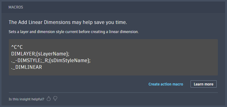 |
If viewing insights in the Autodesk Account portal or My Insights email, see the Using a Recommended Command Macro section for how to use the macro recommendation.  |
Current List of Macro Recommendations
The current list of macro recommendations is rather small, since this is currently a working idea to gauge interest and understand the direction in which to proceed. Here are the macros you might see as recommendations:
- Copy Rotate
-
Copies and then rotates the selected objects.
Runs the MOCORO command to simplify the transition of copying and then rotating the previously selected objects.
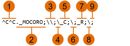
Macro string: ^C^C._MOCORO;\\;\_C;\;_R;\;
- Add Linear Dimension
-
Sets a layer and dimension style current before creating a linear dimension.
Defines the layer which new dimensions are to be placed and then sets a dimension style current before starting the DIMLINEAR command.
Macro string: ^C^CDIMLAYER;{sLayerName};._-DIMSTYLE;_R;{sDimStyleName};._DIMLINEAR
- Multiple Fillet
-
Setup for and create multiple fillets.
Allows you to enter a fillet radius and then continuously specify multiple objects to extend/trim and add a fillet at the intersections of the selected geometry.
Macro string: ^C^C._MULTIPLE;._FILLET;_R;
- Purge Save
-
Purges unused layers and styles from a drawing before saving the drawing.
Purges unused named objects with the PURGE command and then performs a quick save with the QSAVE command.
Macro string: ^C^C._-PURGE;_ALL;;_N;._QSAVE;
Using a Recommended Action Macro
When My Insights recommends this type of macro, click the Create Action Macro option to create a new drawing and run a sequence of commands that results in the recording of a new action macro. The action macro is saved to your local drive and can be edited, played back, or shared with others. If you want to learn how to record your own action macros or share action macros with others, see Have You Tried: Putting the Action into Macros.
The following steps provide an overview of editing a recorded value of an action macro:
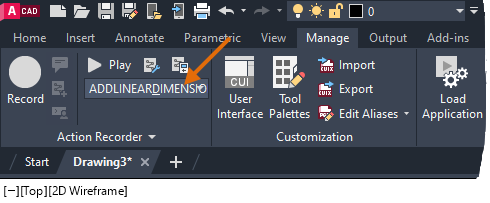
- From the ribbon, click Manage tab > Action Recorder panel and then choose the macro to edit from the Action Macro drop-down list.
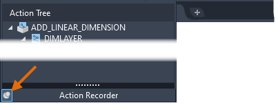
- Click the title of the Action Recorder panel to expand it.

- Click the pin button to keep the panel from collapsing.
- In the Action Tree, right-click over a value node and choose Edit.
Here are some of the data types a value node might represent
 Layer or object color
 Layer or dimension style name
 Fillet radius or length
 Angle of rotation
 Absolute coordinate point
For a full list of the node types in an action macro, see Action Node Icon Reference.
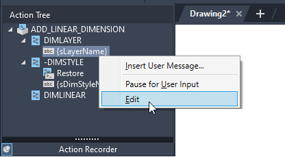
- Type the new value and press Enter.
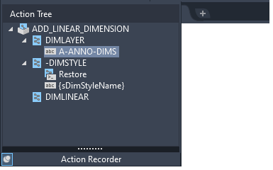
- Repeat steps 4 to 5 for each value node that needs to be edited.
- When done editing the action macro, click the pin button again to allow the panel to collapse.
To use an action macro, do one of the following:
- At the Command prompt, enter the name of the macro just like you might for a standard AutoCAD command, such as LINE or ERASE.
- From the ribbon, click Manage tab > Action Recorder panel and choose the macro to playback from the Action Macro drop-down list. Once a macro has been chosen, click Play.
If you want to remove a previously recorded action macro, follow these steps:
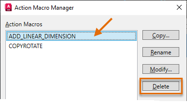
- From the ribbon, click Manage tab > Action Recorder panel > Manage Action Macros (or enter ACTMANAGER at the Command prompt). Find
- In the Action Macro Manager dialog box, choose the action macro to remove and then click Delete.
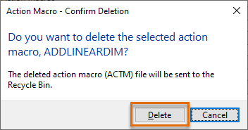
- In the Action Macro – Confirm Deletion message box, click Delete.
- Click OK to close the Action Macro Manager dialog box.
Using a Recommended Command Macro
When My Insights recommends this type of macro, you need to copy the macro string to the Windows Clipboard to use it. A command macro is defined as a series of commands and expected options and values with a specialized syntax. The syntax of a command macro is similar to the input you enter at the AutoCAD Command prompt with some additional special characters. If you want to learn how to define your own command macros, see About Command Macros and Have You Tried: Design Your Own Ribbon.
The following lists the most used special characters in command macros:
- ^C – Represents pressing the Esc key.
- . (period) – Instructs AutoCAD to use the standard definition of a command. The behavior of commands can be altered with programming languages like AutoLISP and ObjectARX.
- _ (underscore) – Lets AutoCAD know the command or option provided is the global/English name. This is required for macros to work correctly across multiple languages.
- ; (semi-colon) – Represents pressing the Enter key.
- \ (backslash) – Represents a pause for user input; allows the user to enter a value, specify a point, or select objects.
- (space) – Represents pressing the Spacebar key.
Here is what the Copy Rotate macro looks like at the AutoCAD Command prompt and how its syntax looks as a command macro:
| Command Prompt Sequence | Macro Syntax Equivalent |
|---|---|
Command: MOCORO Select objects: Specify opposite corner: Select objects: Base point: [Move/Copy/Rotate/Scale/Base/Undo]<eXit>: C Second point of displacement/Undo/<eXit>: Second point of displacement/Undo/<eXit>: [Move/Copy/Rotate/Scale/Base/Undo]<eXit>: R Second Point or Rotation angle: [Move/Copy/Rotate/Scale/Base/Undo]<eXit>: |
MOCORO; \ \ ; \ C; \ ; R; \ ; |
Here is what the final macro might look like:
 |
|
The following steps provide an overview of defining a command macro in the current customization (CUIx) file:
- From the insight card, do one of the following:
- If there is a Copy to Clipboard option, click it to copy the macro string to the clipboard.
- If there is no Copy to Clipboard option, highlight the macro string in the box. Then right-click and choose Copy (or press Ctrl+C).
- In AutoCAD, from the ribbon, click Manage tab > Customization panel > User Interface. Find
- In the Customize User Interface (CUI) Editor, under the Commands pane, click Create A New Command.

- In the Properties pane, in the Name field, double-click and replace the default text of "Command1" with the name of the macro, such as "Copy Rotate" or "Multiple Fillet".
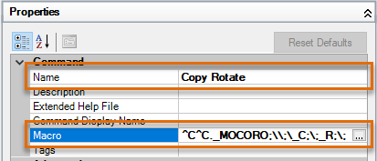
- Click in the Macro field and then click the Ellipsis button [...].
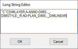
The Long String Editor dialog box opens.
- Select the current text. Then right-click and choose Paste (or press Ctrl+V) to paste the copied macro string from Step 1.
- If the macro string appears on multiple lines, click at the end of each line and press Delete once.
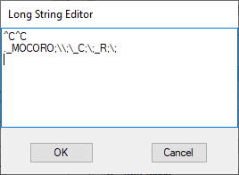
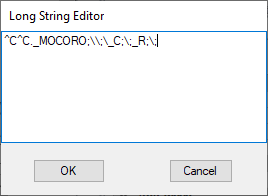
All carriage returns should now be removed from the copied macro string resulting in the macro string being on a single line. The macro string might still wrap based on its length though.
- If the macro string contains placeholders, values surrounded by curly brackets { }, select the curly brackets and the text between them. Then enter a meaningful value for your environment.
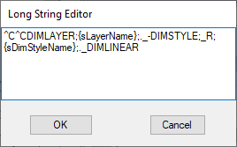
For example, the "Add Linear Dimension" macro contains the following placeholders:
- {sLayerName} – Replace this string with the layer name on which you frequently place your dimensions
- {sDimStyleName} – Replace this string with the dimension style you frequently assign to your dimensions
- Click OK to exit the Long String Editor dialog box.
- Click in the Small Image field and enter
RCDATA_16_COPYOB.
RCDATA_16_COPYOB is the name of the icon assigned to the COPY command. You can use the Button Image pane to find the name of one of the icons that ship with AutoCAD. You can also choose a custom icon by clicking the Ellipsis button […]. Custom icons should be 16x16 or 32x32 pixels in size.
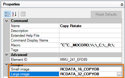
- Click in the Large Image field and enter RCDATA_32_COPYOB.
- Click Apply to save the changes.
Now that you have created a command with the recommended macro, the following steps explain how to add the custom command to the Quick Access toolbar:
- In the Customize User Interface (CUI) Editor, under the Commands pane, select the command you just created.
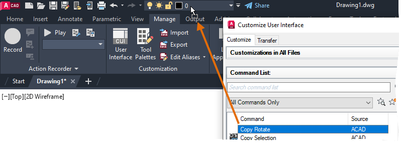
- Click and drag the command onto the Quick Access toolbar (QAT) at the top of the AutoCAD application window.
- Move the mouse pointer over top of an existing button or control on the toolbar.
- When you see the cursor change to an arrow with a rectangle, release the mouse button to add the new command and shift the existing button to the right.

- Click OK to save the changes and exit the CUI Editor.
- Click the new button on the QAT to test the macro.
- As needed, open the CUI Editor to make changes to the custom command and its macro, or create new macros based on your needs.
While adding a command to the QAT is convenient, it isn’t the best place to add and organize many custom command macros. Custom command macros are best organized on the ribbon. For information on how to add commands to ribbon tabs and then display those ribbon tabs, see Have You Tried: Design Your Own Ribbon.