In this exercise you learn how to set options for vectorization tools and convert basic raster geometry into vector entities.
The Vectorization Tools settings are contained in three of the tabs on the Raster Design Options dialog box: Raster Entity Detection, VTools General, and VTools Follower.
The basic elements of any drawing include lines, arcs, circles, rectangles, and polylines.
Related Exercises
Before doing this exercise, ensure that AutoCAD Raster Design toolset options are set as described in the exercise Exercise A1: Setting AutoCAD Raster Design Toolset Options.
Exercise
- In the
..\Program Files\Autodesk\ApplicationPlugins\RasterDesign2022.Bundle\Contents\Tutorials\Tutorial6 folder, open the drawing file
VTools_02.dwg.
Access the Raster Design Options Dialog Box
- To display the
Raster Design Options dialog box, click
Raster
 Options.
- On the
Raster Entity Detection tab, set the
Max Jump Length option to 20.
This setting specifies the maximum length of a gap that AutoCAD Raster Design toolset will tolerate when following a raster polyline. It can be used to jump over labels embedded in the line or to follow non-continuous lines such as dashed lines.
- On the
VTools General tab, ensure that the
Removal Method is set to
REM.
This option erases the underlying raster while preserving intersecting raster data. To completely remove all raster data underneath the new entity, you would use the Rub option.
- Click the
Round Values option, click
Specified Precision, and set the
Length precision to 0.01.
This setting overrides the AutoCAD precision for distances when creating vectors using single-pick options in vectorization tools. However, if you are manually selecting the dimensions, (multi-picking), the chosen points take precedence and the dimensions of the new entity use the AutoCAD precision.
- On the
VTools Follower tab, click
End Current Polyline If Closed Loop Detected.
This option causes new vector polyline entities to finish when a closed boundary or loop is encountered.
- Click OK to close the
Raster Design Options dialog box.
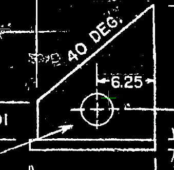
Convert a raster circle to a vector using a single pick
- To create a new circle, click
Raster menu Vectorization ToolsCircle.
- Click a point anywhere on the edge of the circle.
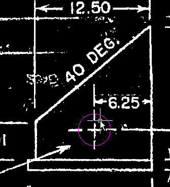
Verify the circle properties
- Enter r to enter a new radius for the circle.
- Enter
1.75 for the new radius.
This forces the new vector circle to match the labeled dimension (3.5 diameter).
- Press
Enter to exit the command.
The command removes the raster data below the new circle, but preserves the intersecting raster dimension lines.
Set a raster snap
- To set a running raster snap, click
RasterRaster Snap.
- Select
Raster Snap On, then click
Clear All.
This activates the raster snaps, and clears the default selections. Raster snaps select points on raster geometry in the same way an OSNAP selects points on vector geometry.
- Select
Corner, then click
OK.
This sets the raster snaps to select a corner where two raster lines connect.
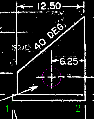
Convert a raster line to a vector using two picks
- To create a new line, click
Raster menu Vectorization ToolsLine.
- Enter 2p to draw the line by selecting two points.
- Select the lower left corner of the base of the part, then the lower right corner.
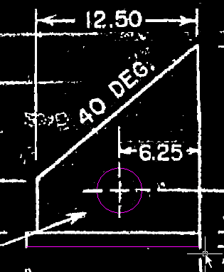
Verify the line properties
- Enter l (Length) to change the length of the line.
- Enter
13.3 for the new length.
This forces the new vector line to match the labeled dimension.
- Enter a (Angle) to change the direction of the line.
- Enter
0 for the new angle.
This forces the new vector line to be orthogonal.
- Press
Enter to exit the command.
The command removes the raster information below the new line.
- Close the drawing without saving changes.