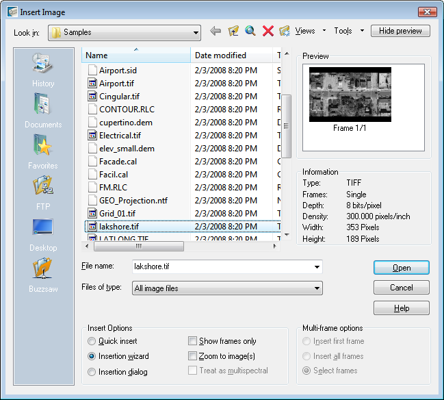
In this exercise you learn to use the Insertion Wizard to guide you through inserting and positioning an image into a drawing.
Related Exercises
Before doing this exercise, ensure that AutoCAD Raster Design toolset options are set as described in the exercise Exercise A1: Setting AutoCAD Raster Design Toolset Options.
Exercise
Choose an image to insert
- In the ..\Program Files\Autodesk\ApplicationPlugins\RasterDesign2022.Bundle\Contents\Tutorials\Tutorial2 folder, open the drawing file Scanned_01.dwg.
- To display the
Insert Image dialog box, click
Raster
 Insert.
- From the Files of Type list, select All Image Files.
- If necessary, navigate to the \Tutorial2 folder.
- Select the image file FoundationDetail_01.tif.
- Review the values shown for each parameter in the
Information box.
This parameter list identifies important characteristics of the image.
The scanned drawing in the image is turned on its side (portrait orientation). In addition, the image, which was scanned from a blueprint, has a light background with line work that is difficult to see.
The values for Depth and Density are important for this image:
- The depth of 1 bit per pixel indicates a bitonal image.
- The density of 200 dots per inch (dpi) indicates that the image was scanned at a low resolution. This low-quality scan may be responsible for some of the problems with this image that you correct in later exercises.

Position and insert the image using the Insertion Wizard
- Under
Insert Options select the
Insertion Wizard option.
Also under Insert Options, ensure that Show Frames Only is not selected.
- Click
Open to display the
Pick Correlation Source dialog box.
This dialog box is the first dialog box of the Insertion Wizard. When you choose a correlation source, the dialog box shows the insertion point, rotation, and scale associated with the selected correlation source.
- Accept the default correlation source, Image File, and click Next.
- Change the rotation value to 90 and click Next.
- Verify the AutoCAD values and click Apply.
- Click Finish to insert the image.
- Zoom to the drawing extents.
The image was rotated 90 degrees when it was inserted.

- Close the drawing without saving changes.