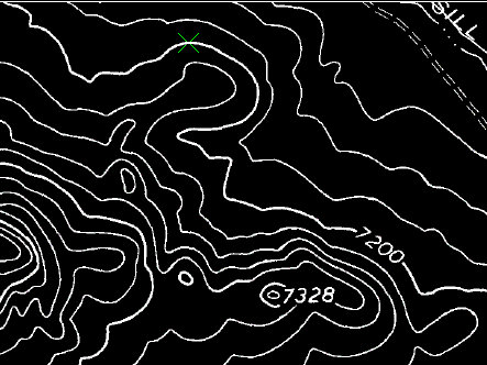
In this exercise you use the contour follower to convert a raster contour to a vector polyline with elevation.
You can convert a raster contour to a vector polyline with elevation using settings to control elevation assignment, layer management, and decision point behavior. Elevation levels can represent ground elevation or another attribute of the terrain, such as temperature or population density.
Related Exercises
Exercise
- In the \Tutorial6 folder, open the drawing file
VTools_06.dwg.
Access the Raster Design Options dialog box
- To display the
Raster Design Options dialog box, click
Raster
 Options.
- Select the
Raster Entity Detection tab and change the
Max Jump Length option to 5.
This setting specifies the maximum length of a gap that AutoCAD Raster Design toolset will tolerate when following a raster polyline. It can be used to draw through labels embedded in the line or to follow non-continuous lines such as dashed lines.
This length is in pixels and can be selected on screen using the Pick button. In this case, the jump length is set to 5 so that the follower does not automatically draw through contour labels.
- Click the
VTools Follower tab. In the
Contour Settings area, change
Elevation to
Prompt, and set the
Elevation Interval to 20.
This setting controls the default elevations displayed for contours as they are converted.
- Click the VTools General tab and click Vector Separation to display the Vector Separation Options dialog box.
- Click the
Contour tab on the
Vector Separation Options dialog box and verify that the option
Separate Contours By Elevation is selected.
This setting assigns contours to layers based on their elevation interval.
- In the
Minor section, set the
Interval to 20 and
Layer to
contour20. In the
Major section, set the
Interval to 100 and
Layer to
contour100. Set the
Polyline Width to
Actual for both the Minor and Major polylines.
These settings ensure that all contours with an elevation divisible by 100 are placed on the contour100 layer automatically. All contours with an elevation divisible by 20, but not by 100, are placed on the contour20 layer. All polylines use a width that matches the original raster data.
- Click
OK to exit the
Vector Separation Options dialog box; click
OK again to exit the
Raster Design Options dialog box.
Create a contour from raster information
- To create contours, click
Raster menu Vectorization ToolsContour Follower.
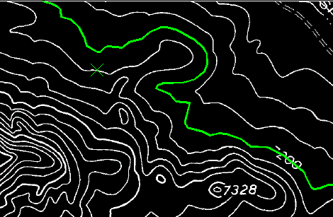
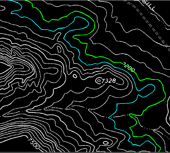
- Click on the upper half of the 7200 contour.
- When the follower reaches the break where the label is located, manually add one or two points across the label, then click on the contour line on the other side of the label.
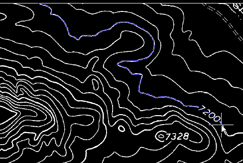
- Enter o (Continue) to continue following the contour to the far end.
- Press Enter to stop the following process.
- Enter
7200 to set the elevation for the new contour.
The new contour is placed on the contour100 layer and the polyline width is set to match the original raster.
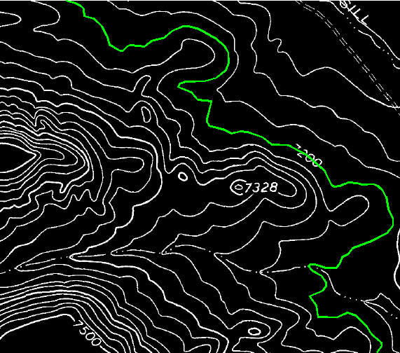
- Click on the 7220 contour, to the left of the 7200 contour. The entire line is followed.
- Press Enter to stop the following process.
- Press
Enter to accept the default elevation of 7220 for the new contour.
The new contour is placed on the contour20 layer and the polyline width is set to match the original raster.
- Close the drawing without saving changes.