Define a REM region object when you want to work with the pixels inside the specified area, such as the pixels within a polygon.
You can define the region using the Raster Entity Manipulation submenu on the Raster menu, the REM Regions toolbar, or the command line.
You can define the following region objects: polygon, rectangle, diagonal, and circular. In addition, you can define a region object from an existing vector object.
After you define a region object, you can edit it, then merge it into an existing image, or create a new image from the region object.
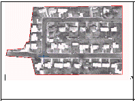
As shown in the following example, you can define a housing development within an aerial photograph as a region object. You can then convert the region object to a new image as a base for a street drawing.
Grip Behavior
Each vertex of a polygonal, rectangular, or diagonal region object has a grip you can use to select the object. Moving a grip moves the object.
A circular region object has five grips: one at the center of the circle and four grips on the circumference.
If you stretch either the start or end grip point of a line, AutoCAD Raster Design toolset redraws the line with the new start or end point, respecting the original line width. When the line is redrawn, AutoCAD Raster Design toolset uses the current AutoCAD linetype.
If you stretch any of the grip points of an arc, AutoCAD Raster Design toolset redraws the arc's start, end, and radius, respecting the original line width. When the arc is redrawn, AutoCAD Raster Design toolset uses the current AutoCAD linetype.