The following example is based on a case study conducted using Trimble and Leica survey data collection equipment. A small site survey was performed to demonstrate that raw survey data from equipment providers can be converted and imported into Autodesk Civil 3D. These companies, and others, directly support Autodesk Civil 3D and demonstrate an advantage that Autodesk Civil 3D has by using the field book file data format.
This section describes best practices for preparing to import survey data into Autodesk Civil 3D. For more information about Survey Field to Finish, see Survey Field to Finish. The basic recommended sequence is as follows:
- Create a code set list in each controller to collect data in a consistent manner. Use a single coding standard such as the codes shown here that were used to code the sample field data.
Entity Code Station STN Football pitch FP Bank Bottom BB Building BG Drop Kerb DK Electricity Pole EP Fence FE Gate G Gulley GU Hedge HE Inspection Cover IC Kerb K Lamp Post LP Manhole MH Manhole-Rectangular MHRECT Marker MK Overhead Wire OHW Post PO Spot Level SL Steps STEP Tank TA Text TXT Tree TE - During the field survey data collection, use the coding convention previously established in an
Autodesk Civil 3D Linework Code Set. For example, it is recommended that the linework command code come after the linework feature name, such as "OHW B", where OHW is the figure name, and B is the begin code defined in the Linework Code Set that will be used when the data is imported into
Autodesk Civil 3D.
If your data collector does not support the use of a Linework Code Set, then a convention such as the figure command BEG is used to indicate the beginning of a figure line, such may be the case with some data collection conversion tools that do not support the Field to Finish features of Autodesk Civil 3D.
Inserting a figure command into the point description during the survey data collection phase of a project automates the process of creating line work when the data is later imported into Autodesk Civil 3D.
- Use the Linework Code Set dialog box, as shown in figure 1, to specify coding methods and to edit special codes, line segment codes, and curve segment codes.

Figure 1: Specify coding methods for consistency
Note:It is recommended that you use <space> as the Field/Code Delimiter Property value.
- Use the Description Key editor, as shown in figure 2, to create a suitable description key set to match these codes to style points, label descriptions, and elevations accordingly.

Figure 2: Create description keys editor
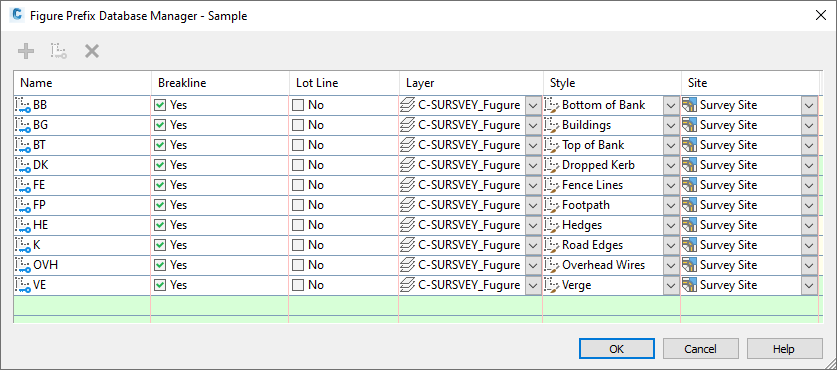
- Use the Figure Prefix Database Manager, as shown in figure 3, to create a figure prefix library and figure styles with which to receive the linework codes and draw the linework in a suitable style.
Note:
You should only specify a site if the Lot Line property is set.

Figure 3: Specify how imported line work is drawn
You can specify whether the linework is drawn as breaklines or lot lines, as well as the assigned layer, style, and site.

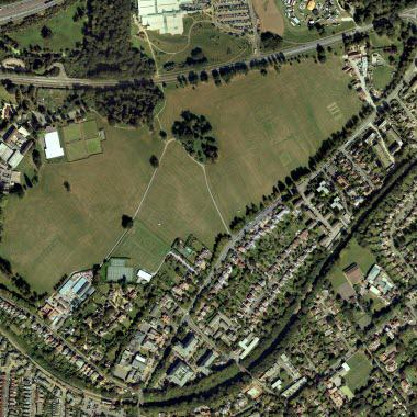
Figure 4: Aerial photo of the site survey field
The following two steps in this workflow illustrate the results of importing and working with the sample survey data. The example in this workflow is the field shown in figure 4.
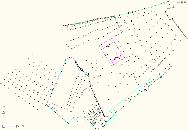
- Import the survey data. The results after importing the survey data into
Autodesk Civil 3D are shown in figure 5.

Figure 5: Imported survey data
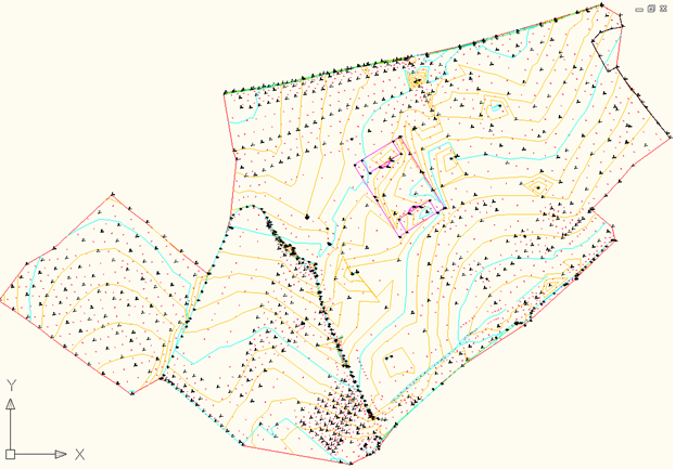
- Create a surface from breaklines and point groups. Then specify a contour style as shown in figure 6.

Figure 6: Surface created from breaklines and point groups with specified contour style
This completes the survey field to finish workflow.
Importing Survey Data
The Survey collection equipment described in this section is compatible with Autodesk Civil 3D.
Use the following software to convert survey data:
Trimble
Use the Trimble Link add-on to Autodesk Civil 3D (available from www.trimble.com), to connect directly to the equipment controller and/or to the location where the raw .job file is stored.
When the data is checked in, the link will check for any alphanumeric point numbers and change them accordingly, as these are not catered for.
Leica
The Leica X-Change software (www.leica-geosystems.com), uses the DBX database as the raw survey data format. The X-Change add-on to Autodesk Civil 3D converts the raw format to a field book file, that can be imported into Autodesk Civil 3D.