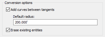
If you are creating an alignment from a polyline, adapt your method to the nature of the polyline. The dialog box for creating an alignment in this way includes a check box for Add Curves Between Tangents, shown in figure 1.

Figure 1: Detail from alignment creation dialog box
If you select the Add Curves Between Tangents check box, you get an alignment with free curves inserted where two straight segments joined. These free curves are easy to edit, as they retain tangency at all times. If your input polyline includes arcs, these become fixed curves in the alignment, which do not retain tangency in editing. Leaving these as fixed curves is fine if you do not need to edit them. An alternative is to delete these fixed curve subentities and insert a free curve between the adjacent entities. Then if you need to edit the alignment, the free curve retains tangency.
Entity Types
If you are laying out alignments using the drafting tools, it can be overwhelming to see the wide range of line, curve, and spiral tools. To make the correct choice, it helps to understand the difference between fixed, floating, and free entities:
- Fixed entities are defined by specific points, with no topological relation to adjacent entities. In editing operations, fixed entities remain connected to adjacent entities, but can be moved out of tangency. This is the type of entity you get when you convert a polyline to an alignment.
- Floating entities are attached to an existing entity and remain tangent to it. Their endpoint, however is defined by other criteria, such as radius, length, a through point, or finding the best-fit path through a number of specified points.
- Free entities are always created between two existing entities, and always maintain tangency to them. Free entities are the most flexible in editing operations.
Once you determine which entity type best suits your design context, you can select the appropriate line, curve, spiral, or combination based on your available design data, such as whether you have a known through point, length, or radius.