To place the label, specify the alignment and the component in the drawing, such as a line, curve, or spiral segment. Select either a single segment or intersection or label the whole alignment using the multiple options.
Note: Rail alignments may be measured using either the curve's true geometry or the chord length. If you use a General Curve label curve length, the value in the label always displays the true curve geometry length, and not the chord length. To label a curve's chord length, you must use an expression to determine the chord length.
To label multiple alignment line segments
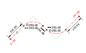
Automatically label all lines, curves, and spirals in the alignment with Line, Curve, and Spiral label styles.
Labels are placed on each line, curve, and spiral entity in the selected alignment.

- Click


 .
. - In the Add Labels dialog box, verify that Alignments is displayed in the Feature list.
- In the Label Type list, select Multiple Segment.
- Specify label styles for Line, Curve, and Spiral.
- Click Add. In the drawing, select the alignment.
Labels are displayed on all lines, curves, and spirals in the alignment.
To label alignment line segments
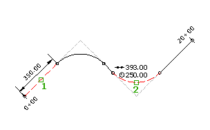
Add single segment labels to the lines, curves, or spirals with Line, Curve, and Spiral label styles.
Labels are placed on each line (1), curve (2) or spiral entity that you select.

- Click


 .
. - Select a location on the alignment line or segment to label.
- In the Label Type list, select Single Segment.
- Specify label styles for Line, Curve, and Spiral.
- Click Add. In the drawing, select the alignment.
- In the drawing, select the segments you want to label.