Part compare is a feature of RapidCut simulation that enables you to compare the results of a toolpath simulation with the actual solid part model.
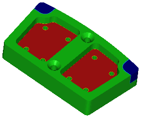
Regions that are properly cut are displayed in green. Regions where extra material remains are shown in light blue (small amount of rest material) through to dark blue (larger amount of rest material). Gouged regions are shown in yellow (small gouge) through to red (large gouge), for example:
To use part compare:
- Right-click the solid in the graphics window and select Use Solid As Part Compare Target from the context menu.
- Specify the part compare settings and tolerances on the Part Compare page of the File > Options dialog.
- Run a 3D RapidCut simulation.
- Select Home tab > Simulation > Show > Part Compare.
To view the actual part model that the simulation is compared with, select Home tab > Simulation > Show > Target Part.
Note: If you adjust the view after a part compare has been performed, a new RapidCut simulation is performed automatically, but you must run another part comparison.
Part compare also works with the region of interest.