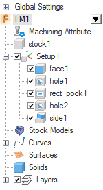
The Part View panel displays a hierarchical view of the part. Each Setup is listed with each of the features of the Setup listed below. From this view you can select, show, hide, or edit features.
To use the part view:
- Click
 next to an item to expand the view and show the item's sub-items. Click
  to collapse the view and hide the item's sub-items.
 - Move the cursor over an item's name to highlight it in green in the graphics window. Use this to distinguish between overlapping items and find items in complex documents.
- Click an item's name in the Part View to select the item. Selected features are highlighted in red in the graphics window.
- Right-click an item to display the context menu to perform an action on the item. Alternatively, click
 next to the selected item.
 - Features have a check box next to their name. When you deselect the feature, it is excluded from the next toolpath generation.
- All objects, except geometry, are represented in the Part View.
- You can select multiple items in the part view by using Shift+click and Ctrl+click.
|
Symbol |
Meaning |
Notes |
|---|---|---|
|
|
Document |
Displays the name of the current document. Use the right-click context menu to Include All Features or Exclude All Features in the current document. |
|
|
Machining Attributes |
Double-click the icon to display the Machining Attributes dialog where you can specify the default machining attributes. |
|
|
Stock |
If you select the stock name in the Part View, the stock is highlighted in red in the graphics window. Double-click the stock name to open the Stock Properties dialog. You can show, hide, and center the stock from the context menu. |
|
|
Setup |
The features belonging to the Setup are listed below each Setup name. |
|
|
Feature |
If you select a feature name in the Part View, the feature is highlighted in red in the graphics window. |
|
|
Pattern or Group |
A pattern or group of features. If you select a pattern or group name in the Part View, the pattern or group is highlighted in red in the graphics window. |
|
|
Stock Models |
Lists any stock models in the document. Select Add Stock Model from the context menu to open the Add Stock Model dialog. |
|
|
Tool Posts |
Lists the tool posts for multi tool post Turn documents. You can change the tool post names in the CNC file. |
|
|
Curves |
Lists the curves in the document. If you select a curve name in the Part View, the curve is highlighted in red in the graphics window. |
|
|
Surface |
If you select a surface name in the Part View, the surface is highlighted in red in the graphics window. |
|
|
STL |
Lists STL solid model files that have been imported into FeatureCAM. Select an STL name in the Part View and the STL is highlighted in red in the graphics window. |
|
|
Solids |
Lists the solids in the document. If you select a solid name in the Part View, the solid is highlighted in red in the graphics window. |
|
|
Layers |
Lists the layers in the document. |


