Revolved Solid creates a solid design feature by revolving a curve around a line.
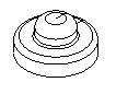
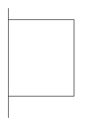
This example shows a base solid created with a curve on the axis revolved 360°. You can tell that the curve was on the axis because there is no hole in the middle.
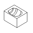
This example is an extrude cut design feature rotated 180°:
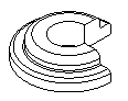
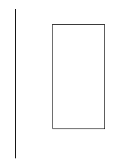
This example shows a base solid created with a curve off the axis (note the hole in the middle) and revolved 270°:
To create a solid of revolution design feature:
- Select Construct tab > Solids panel > From Curves > Revolve to display the Revolved Solid dialog.
- Optionally enter a Name for the solid, or leave the default name.
- Select the curve name in the
Curve list or click the
Pick Curve
 button and select the curve in the graphics window.
- Pick the Construction method. This is where you set what is revolved around, or the pole. You can pick a Custom line, X-Axis, Y-Axis, or Z-Axis.
- If you selected
Custom line, select the name of the line in the
Axis list or click the
Pick Line
 button and select the line in the graphics window.
- Enter the Start angle in degrees.
- Enter the End angle in degrees.
- Select the type As New Base Solid, As Add, or As Cut.
- Click the Preview button to see a line drawing of the feature.
- If the cut is on the wrong side of the curve, click Flip Side to Cut and click Apply again to verify.
- Click OK.
Using open curves for solids of revolution
If the curve is open, a dialog is displayed with the following options:
Close curve using lines to axis — This creates a straight line from the curve endpoints to the axis.
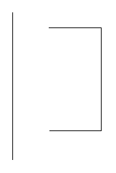
Close curve by joining endpoints — This creates a straight line between the endpoints of the curve:
Continue with curve as-is — No change is made to the curve and a sheet is created.