You can use the Surface control tab of the Surface Milling Properties dialog to specify how the toolpaths are generated on surfaces.
The Surface list displays all surfaces in the feature. Deselect the check box next to a surface name to exclude it from the operation.
Select a surface in the list to highlight it in the graphics window, or use the
Pick surface
 button and select a surface in the graphics window to highlight it in the list.
Isoline milling
Attributes for — displays the operation being edited.
-
Surface — The surfaces are machined in the order listed. Use the
 and
and
 buttons to rearrange the surfaces in the list. Deselect the check box next to a surface name to exclude it from the operation.
-
Start Curve — Isoline surfaces are made up of rows or columns of curves. The
Start Curve determines the first isoline curve used for machining the surface. Click
Set isoline row/col
 to change the starting isoline curve.
First Row — the tool cuts along the row isoline curves, starting with the first row.
Last Row — the tool cuts along the row isoline curves, starting with the last row.
First Col — the tool cuts along the column isoline curves, starting with the first column.
Last Col — the tool cuts along the column isoline curves, starting with the last column.
-
Cut direction — Determines the direction that the tool cuts along the isoline curves. Click
Cut direction
 to change the direction between
increasing and
decreasing.
to change the direction between
increasing and
decreasing.
-
Sequence — Determines the sequence in which the tool cuts the isoline curves. Click
Sequence
 to cycle through the toolpath sequence options.
- None — the tool cuts the isoline curves in order.
- In to out — The tool starts at the middle and cuts towards the outside in both directions.
- Out to in — The tool starts at the outside and cuts towards the middle from both directions.
An axis is displayed in the graphics view which shows the location and direction of the start of the toolpath for the selected surface:
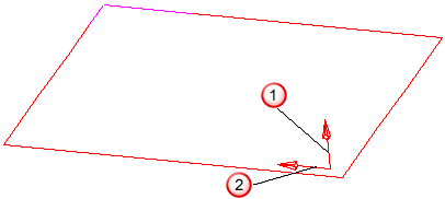
 Machining side arrow
 Isoline row column corner and direction
Flowline milling
If you select a Flowline guide surface, the isolines of another surface are projected onto all the surfaces of the feature.