You can use the Surface Milling Properties dialog to edit the properties of a 3D Surface Milling feature.
To display the Surface Milling Feature Properties dialog, double-click a Surface Milling feature in the graphics window or Part View panel.
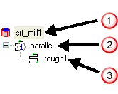
The 3D Surface Milling Properties dialog lists the strategies and operations in the tree view. The tabs displayed in the dialog change depending on which level in the tree view you select.

 Feature
 Strategy
 Operation
Feature-level tabs
The top level of the tree view is the feature level. Select the feature name at the top of the tree view to access these tabs:
Dimensions — Use this tab to specify the part and check surfaces
Location — Use this tab to reposition the feature relative to the surface
Process — Use this tab to create, delete and reorder the operations of the feature
Machining Side — Use this tab to control which side of surfaces to machine
Misc — Use this tab for a variety of feature-level attributes
Strategy-level tabs
The next level is the strategy level. Select a strategy in the tree view to access the following tabs:
Strategy — Use this tab for rough/finish classification, edge protection, and re-machining
Edges — Use this tab to choose how the tool behaves at the limits of the part surfaces as seen from the top view.
Stock — Use this tab to choose the clipping curves for the material to be removed
Slopes — Use this tab to set slope angle limits for restricting toolpaths
Surface Control — Use this tab to exclude feature surfaces for specific operations
Operation-level tabs
The third level is the operation level. Select an operation in the tree view to access the following tabs:
Tools — Use this tab to view selected tool or change to a different one
F/S — Use this tab to view automatically calculated feed or speed or change feed or speeds
Coolant — Specify which coolant types to use.
Post Variables — This tab controls post variables, which you can use to pass information to the post-processor.
Milling — Use this tab to set operation-level attributes
Leads — Use this tab to control leads and ramps