The Chamfer feature creates an edge break along a curve with a chamfering tool.
|
|
|
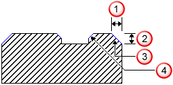
 Width
Width
 Depth
Depth
 Outside
 Inside
To chamfer the entire upper edge of a curved feature, use the optional Chamfer parameter on that feature. Use the Chamfer feature to chamfer only a portion of the edge of a feature.
FeatureCAM follows this general process to create a Chamfer feature:
- Chooses a
chamfer mill tool automatically from the current tool crib, based on:
- the width and depth of the Chamfer,
- the tightest bend in the curve,
- and the corner radius and inner diameter of the rounding tool.
FeatureCAM considers the tool and Inner diameter to pick a tool that has the exact width definitions to cut the Chamfer feature. The inner radius of the tool is important because the tool must fit into tight corners of the curve.
The width of the tool must be large enough to cut the depth and width set for the chamfer.
If a tool that meets the criteria cannot be found, an error is displayed and NC code is not generated.
You can override the automatic tool selection and select a countersink tool. If you are using a countersink tool, you may need to adjust your touch-off point to mill an accurate chamfer.
You can change the default tool used for chamfer operations on the Tool Selection page of the Machining Attributes dialog.
- Determines feeds and speeds based on the stock material being machined. FeatureCAM chooses feeds and speeds for all of its milling using the Feed/Speed database that you can customize.
- Generates a roughing pass.
The important aspects of roughing are as follows:
-
Getting to depth
— The tool must get to depth. This is accomplished by a plunging move.
- Horizontal step — The horizontal step size is controlled by the Distance between cuts attribute on the Stepovers tab. If there is only one pass, there is no horizontal step move.
- Finish allowance — The parameter that determines the amount of material to leave after the roughing pass. By default this is 0.02.
- Generates a finishing pass. By default, the finish pass is turned off and the entire feature is machined by the roughing pass. You can change this on the
Strategy page.
The important aspects of finishing are:
-
Tool selection
— After roughing, the roughing tool is used to finish the Chamfer.
Use Finish Tool commands
FeatureCAM to choose a separate finishing tool (that has the same characteristics unless you override them).
- Horizontal step — The horizontal step size is controlled by the Distance between cuts attribute on the Stepovers tab. With only one pass, there is no horizontal step. The contact point of the tool is controlled by the Chamfer depth attribute.
- Finish passes and overlap — The tool goes around the chamfer a number of times set by Finish passes, and overlaps the starting point by an amount controlled by Finish overlap.
- Retract — This removes the tool from the stock area and sets up for the next operation.
- To edit all instances of this type of feature in the current document, use the Machining Attributes dialog.
- To edit a single feature, use the Tools, Milling, Strategy, and Misc. tabs for the feature in the Feature Properties dialog.
You can edit this process in these places:
The tooling database also has a large impact on how a feature is machined, and the feed/speed database helps to determine the feeds and speeds used.