You can perform 5-axis engraving using a 2D spiral toolpath. This enables you to use a tool axis angle normal to the surface to ensure the engraving has a uniform cross-section and depth of cut.
To create a 5-axis surface engraving feature:
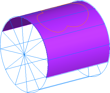
- Create a surface below the stock boundary to determine the depth of the engraving, for example:

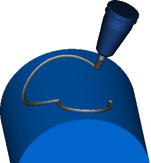
- Create the curve to define the shape of the engraving feature, for example:
- Create a surface milling feature with a 2D spiral operation.
- Double-click the feature in the Part View to display the Feature Properties dialog, and select spiral2d in the Tree View.
- In the Stock tab, under Choose the drive curve, select Select curves for boundaries and click Curve Options.
The Boundary Curve dialog is displayed.
- Under Boundary curve type, select Wall only.
This creates a toolpath along the curve, instead of an area clearance toolpath inside or outside the curve.
- Under Boundary curves, click Boundaries.
The Select Boundary Curves dialog is displayed.
- Select the curve that defines the shape of engraving, and click OK to close the Select Boundary Curves dialog.
- Click OK to close the Boundary curves dialog.
- On the 5-Axis tab, select Use Lead and Lean, and in the from list, select Contact normal.
This keeps the tool axis normal to the surface.
- Click OK to close the Feature Properties dialog.
Tip: You can use the Construct > Curve > From Surface > Project onto Surface menu option to project a curve onto a surface.