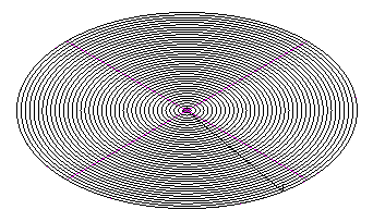
2D Spiral toolpaths mill a feature with a pattern of offset toolpaths. The pattern is obtained by taking the stock boundary, the feature boundary or the curve specified on the Stock tab and offsetting this curve toward the center of the part. The pattern can be cut either towards the feature center or away from the feature center.
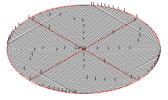
The steps between the passes are calculated in 2D. For spiral toolpaths that use a 3D stepover use the 3D spiral technique. To use the stock boundary, select Use stock dimensions on the Stock tab. This results in a square shape to the toolpaths.
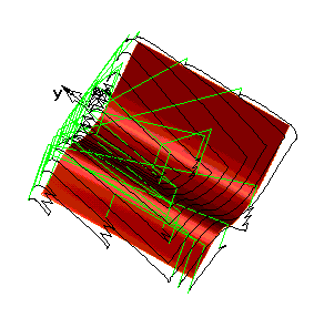
To automatically calculate the silhouette boundary of the surfaces of your feature, select Use part surface dimensions. This toolpath mimics the boundary of your feature.
If you want to use a different curve as your toolpath shape, select the Select curves for boundaries option on the Stock tab. The options for using a curve are different for spiral milling and other techniques.
See also: