Use this section of the 4-Axis or 5-Axis tab to specify how FeatureCAM automatically tilts the tool axis to avoid collisions between the shank and holder of the tool assembly and the model.
No tilting — This is the default setting and means that the holder and shank are not gouge-checked.
Lean — If a collision is detected, the tool axis moves from the original axis in the Lean direction until the collision is avoided.
Lead — If a collision is detected, the tool axis moves from the original axis in the Lead direction until the collision is avoided.
Lead then Lean — If a collision is detected, the tool tilts from the original axis in the Lead direction until the collision is avoided. If the collision cannot be avoided by tilting the tool in the Lead direction, the tool tilts in the Lean direction until the collision is avoided.
Lean then Lead — If a collision is detected, the tool tilts from the original axis in the Lean direction until the collision is avoided. If the collision cannot be avoided by tilting the tool in the Lean direction, the tool tilts in the Lead direction until the collision is avoided.
To Point — If a collision is detected, the tool is aligned with the tip pointing towards the specified point, to become a Toward Point Tool Axis, until the collision is avoided.
From Point — If a collision is detected, the tool is aligned with the tip pointing away from the specified point, to become a From Point Tool Axis until the collision is avoided.
Towards the surface normal — If a collision is detected, the tool axis moves from the original axis and move towards the Surface normal direction until the collision is avoided.
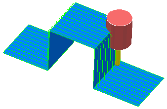
This simple example uses an X-parallel toolpath over a step to show the effect of Collision Avoidance. If you create a simple parallel toolpath over this, you get collisions of the shank as it climbs or descends the step:
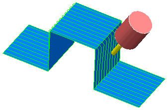
One way around this is to increase the length of the tool. Another way is to change the toolpath strategy. The third way is to use Collision Avoidance. In this case, the initial Tool Axis is Vertical. Select a Tilt Axis for Gouge Avoidance of Lead.
Create a new parallel toolpath. You can see that the toolpath now tilts on the steep portions to avoid the tool holder colliding:
However, the toolpath is still 3-axis on the flat portions where the tool holder does not collide:
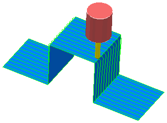
In summary, the tool tries to respect the original Tool Axis Definition for as much of the toolpath as possible. When this is not possible, the tool axis changes in the direction specified in the Tool Tilt Axis field until the tool assembly no longer collides.
Lead then lean
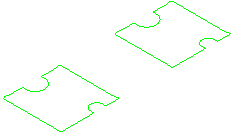
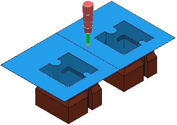
The following example model can be machined using 5-axis simultaneous machining:
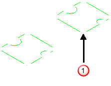
A
Tilt Axis of
Lean does not create a toolpath in the corners
 :
:
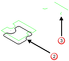
A Fixed direction and a Tilt Axis of From curve creates an incomplete toolpath.
|
|
|
 - the curve used to generate the toolpath.
 - an incomplete toolpath.
The only way to resolve this would be to create a curve in each pocket and generate a separate toolpath for each pocket.
A Tilt Axis of Lead then lean achieves the required result with one toolpath, so there is no need to create any additional geometry.