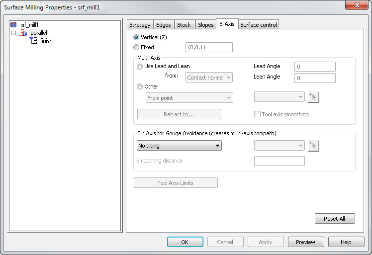
You can use the 5-Axis tab of the Surface Milling Properties dialog to edit the Multi-Axis options of a Surface Milling feature.
For a turn/mill document with a B-axis enabled post (.cnc file) or a 5-axis positioned document, these surface milling operations have a 5-Axis tab:
|
Parallel finish Z-level finish Isoline 2D spiral |
3D spiral Flowline 5-axis trim Swarf |
Horizontal + Vertical Pencil Corner Remachining Between 2 curves |
The strategy type determines the options that are available.
This tab enables you to set three different things: Tool Axis, Tilt Axis for Gouge Avoidance, and Tool Axis Limits. The first two sections of the dialog can be confusing because they both control the tilt of the tool axis. Think of the first section, Tool Axis, as a first level of tool tilting, controlled in a manual way. And then you can add extra tilting to avoid gouges with the tool holder by using Tilt Axis for Gouge Avoidance.
The Tool Axis enables you to define the tool orientation. The default value is Vertical, which is used for standard 3-axis machining. However, it can also be a continuously changing orientation for so-called 5-axis simultaneous machining.
Vertical (Z) — The tool remains aligned with the Z-axis of the active Setup and so is the same as for standard 3-axis milling.
Fixed — This option enables you to set the tool axis direction as a vector.
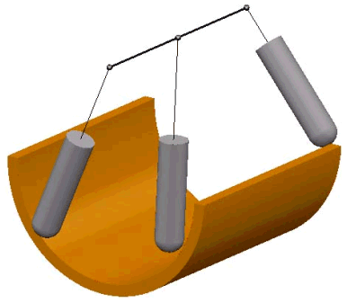
Use Lead and Lean — The tool tilts at a fixed angle relative to the direction of tool travel.
-
from — Select where the lead and lean angle is measured from.
- Contact normal — Select this option to lead and lean from the surface normal at the contact point.
- Vertical — Select this option to lead and lean from the Setup's Z direction.
- Travel dir — Select this option to lead and lean from the perpendicular to the direction of movement
- Legacy — Select this option to use the traditional lead and lean style.
- Lead Angle — This tilts the tool forwards or backwards along the travel direction.
- Lean Angle — This tilts the tool to the left or right of the travel direction.
Other
-
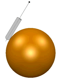
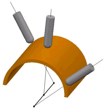
From point — This option aligns the tip of the tool away from a fixed point. The angle of the tool is constantly changing. The tip of the tool moves significantly while the head of the machine tool stays relatively still.
-
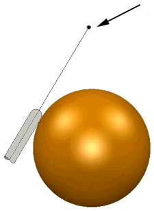
To point — This option aligns the tip of the tool towards a point. The angle of the tool is constantly changing. The head of the machine tool moves significantly while the tip of the tool stays relatively still.
-
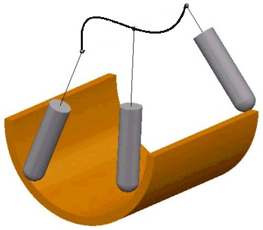
From line — This option aligns the tip of the tool away from a fixed line. The angle of the tool is constantly changing. The tip of the tool moves significantly while the head of the machine tool remains relatively still.
-
To line — The tool tip always tries to point towards the fixed line. The angle of the tool is constantly changing. The head of the machine tool moves significantly whilst the tip of the tool stays relatively still.
-
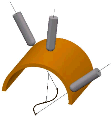
From curve — This option aligns the tip of the tool away from a fixed curve. The angle of the tool is constantly changing. The tip of the tool moves significantly while the head of the machine tool stays relatively still.
-
To curve — This option aligns the tip of the tool towards a curve. The angle of the tool is constantly changing. The head of the machine tool moves significantly while the tip of the tool stays relatively still.
Automatic — The swarf operation has an automatic option (instead of the above Other option). The automatic option tilts the tool to keep the side of the tool in contact with the surface(s) being cut.
Retract to — Click the Retract to button to open the Safe Area dialog.
Tool axis smoothing — This minimizes changes in velocity and position of the tool axis. This smooths the axis movements of the machine tool.
It works by smoothing the rotary axis motion on the A/B axis (Elevation) and the C axis (Azimuth) of a machine tool.
The benefits of using tool axis smoothing include:
- Improved surface finish due to a reduction in jerky motion and reduction of surface dwell marks.
- Reduced machining time due to a more constant rotary axis speed.
- Improved quality of all 5-axis machining strategies.
Tilt Axis For Gouge Avoidance — This enables you to tilt the tool to avoid gouging the model with the holder, in a user-defined way.
Smoothing distance — When using Tilt Axis for Gouge Avoidance, set this attribute to avoid sudden tool axis changes.
Tool Axis Limits — This enables you to define limits on the direction of the tool axis whilst cutting a multi-axis toolpath.