Vortex machining is an area clearance strategy that rapidly removes material from a 3D part while controlling tool load. Vortex is best suited to solid carbide tools and is frequently used in combination with step cutting.
It is an offset-style toolpath and has these main features:
- The engagement angle never exceeds, by more than 15%, that produced by a straight line cut with a given stepover. This eliminates excessive tool load and all full-width cuts. This enables you to increase feed rates. For other area clearance toolpaths, the cutting values are based on the tool manufacturer's slot cutting parameters to ensure the tool can sustain full cutting engagement. As the tool approaches the maximum engagement angle for optimum machining, the toolpath changes to a trochoidal path to avoid tool overload.
- The machine tool almost always runs at the specified feed rate. With other area clearance toolpaths, the machine tool automatically slows down as it approaches a corner and the engagement angle increases. Vortex modifies the toolpath so the tool engagement angle is never exceeded and the machine tool achieves the specified feed rate. The only time the machine tool does not run at the specified feed rate is when the model geometry (a slot or corner) is smaller than the smallest radius that the machine can run at full speed.
- Vortex machining cuts with the side of the tool so it is designed for solid carbide tools, but you may be able to use other tools.
- Because FeatureCAM controls the tool engagement, you can increase the depth of cut, which minimizes machining time.
- Vortex machining is frequently used in combination with Step cutting to minimize terracing while maximizing the removal rate.
- Vortex toolpaths are automatically checked for safety.
FeatureCAM checks for:
- plunges into stock.
- excess tool engagement.
- excess depth of cut.
- small arc movements.
To maximize the benefits of Vortex machining:
- Configure the Vortex parameters to suit each machine tool.
- Use Step Cutting to minimize terracing caused by the increased depth of cut.
With optimum settings, Vortex machining greatly reduces machining times.
Creating a 3D Vortex toolpath
To create a 3D Z-level roughing Vortex toolpath, select Vortex on the Strategy tab of the Surface Milling Properties dialog:
The following attributes are available for Vortex toolpaths in the Feature Properties dialog:
F/S tab:
- Feed — Enter the speed the tool cuts into the material. Vortex toolpaths are machined at this cutting feed rate almost all of the time.
Milling tab:
- Vortex min point spacing — Enter the minimum point spacing at which the machine tool can move at the specified feed rate. If the machine tool has too many points to process, it cannot sustain the specified feed rate.
- Vortex min radius — Enter the minimum radius of the internal trochoids. Vortex toolpaths use trochoidal moves to maintain a constant feed rate. Higher feed rates require a larger minimum radius. If you do not override this value, a default value is used, which is suitable for a typical machine tool at the feed rate specified for the operation.
- Vortex Z lift distance — Enter a Z distance to lift the tool during trochoidal moves to avoid contact between the tool and the surface.
Strategy tab
- Non-Cutting Moves — Displays the Vortex Non-Cutting Moves dialog where you can specify whether to retract and increase the feed rate on non-cutting moves.
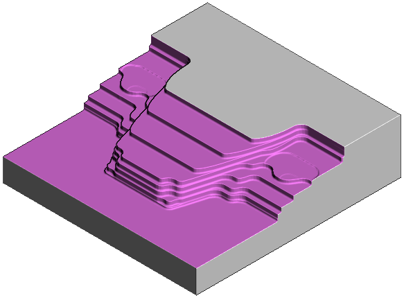
3D Vortex example
This example shows you how to combine Vortex machining with step cutting to rapidly remove material.
Because Vortex machining cuts with the side of the tool, it is designed for solid carbide tools, but there may be other types of tools suitable for Vortex. These tools work best when taking deep cuts with a relatively small stepover.
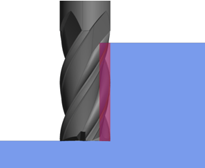
To machine effectively when taking large depths of cut, you must ensure the tool engagement angle never exceeds the specified value. This eliminates excessive tool load and all full-width cuts. FeatureCAM achieves this by introducing trochoidal moves to prevent the tool from exceeding the maximum tool engagement value.
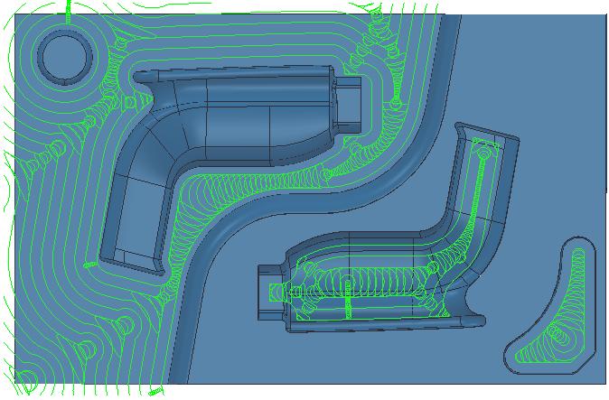
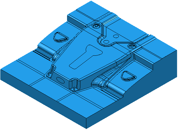
Using a 3D model:
Creating a Vortex toolpath without step cutting.
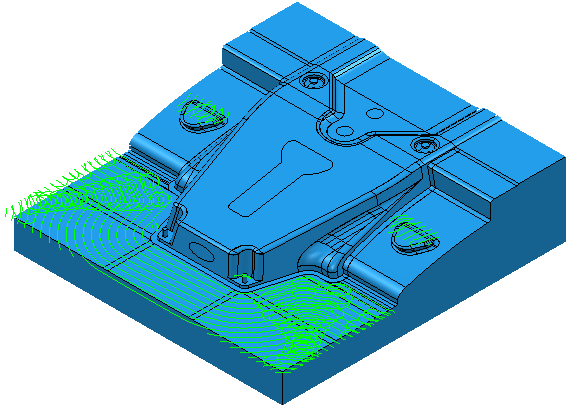
This removes vast quantities of material quickly, but leaves large terraces of unmachined stock on the part.
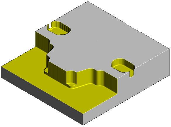
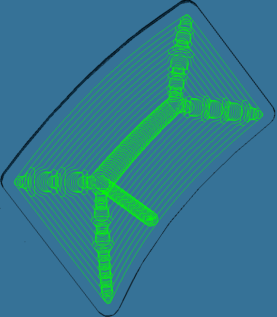
You can minimize the size of these terraces using the Step cutting options.
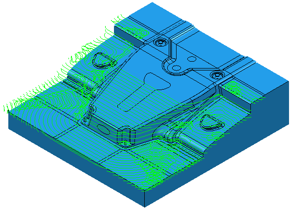
This adds extra machining slices up the part. Looking at a detail of the side view:
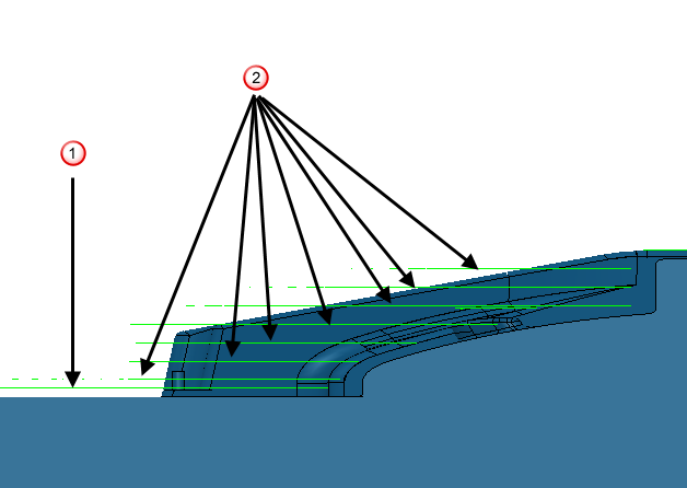
 Original Vortex pass
 Step cutting passes
It also machines more of the excess stock.